Dual sensor system having fault detection capability

a dual sensor and fault detection technology, applied in the field of sensor systems, can solve the problems of inability to detect faults, and inability to implement such a dual sensor system, etc., to achieve the effect of reducing yield, driving up costs, and reducing the cost of implementation

Active Publication Date: 2009-05-21
NXP USA INC
View PDF5 Cites 46 Cited by
  • Summary
  • Abstract
  • Description
  • Claims
  • Application Information

AI Technical Summary

Problems solved by technology

Although sensors are typically designed to be robust, sensor failure can still occur.
The implementation of such a dual sensor system is undesirably complex and large, especially when implemented within the area constraints of MEMS architecture.
A complex and large structure drives up costs and / or reduces yield.
Consequently, this dual sensor design cannot detect faults in real time.

Method used


Image

  • Dual sensor system having fault detection capability
  • Dual sensor system having fault detection capability
  • Dual sensor system having fault detection capability

Examples


Embodiment Construction

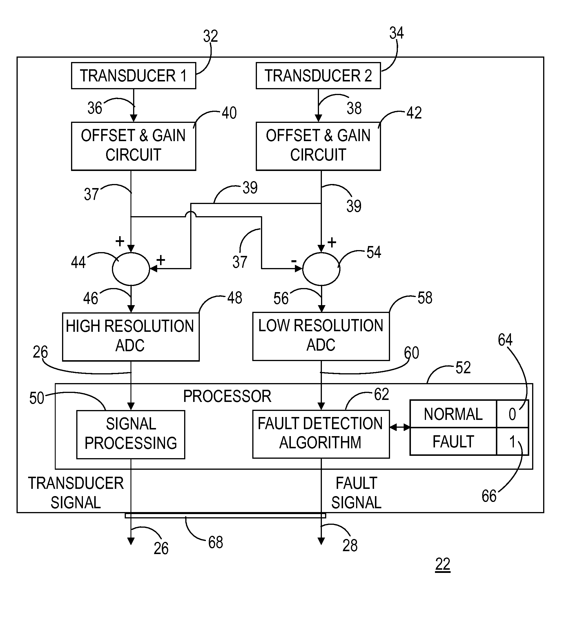
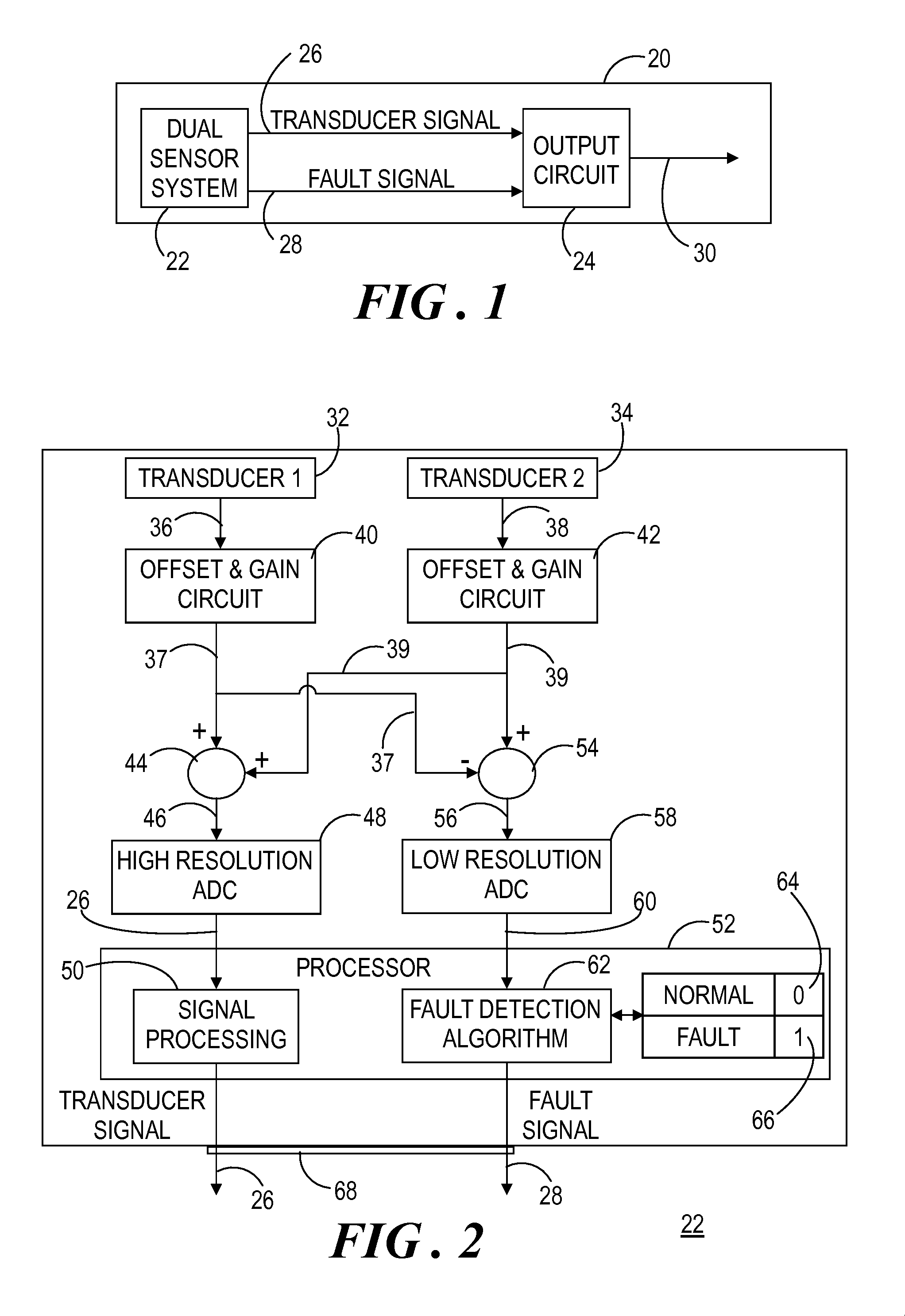
[0010]FIG. 1 shows a block diagram of a device 20 that includes a dual sensor system 22 of the present invention. Device 20 represents numerous systems and devices in which a sensor is incorporated for monitoring and / or controlling the operation of device 20. For example, device 20 including dual sensor system 22 can be realized within an automobile safety application, a machine, aerospace system, a medical device, a robotic device, and the like. Dual sensor system 22 can be used to measure a particular parameter for device 20 such as pressure, temperature, speed, acceleration, motion, proximity, and so forth.

[0011]For purposes of the following discussion, dual sensor system 22 is in communication with a downstream component, for example, an output circuit 24 of device 20. Output circuit 24 receives a digital transducer output signal 26 from dual sensor system 22. In addition, output circuit 24 receives a signal, referred to herein as a fault signal 28, indicative of a condition of ...


PUM


Abstract

A sensor system (20) includes transducers (32, 34) each yielding an analog signal (37, 39) representing a parameter independently sensed by each of the transducers (32, 34). The signals (37, 39) are summed and the resulting transducer signal (46) is converted to a digital transducer signal (26) by a high resolution analog-to-digital converter (ADC) (48). Concurrently, one of the signals (37, 39) is subtracted from the other. The resulting difference signal (56) is converted to a digital difference signal (60) by a low resolution ADC (58). When the digital difference signal (60) is within a threshold window (78), a fault signal (28) indicates a normal condition (80) of the transducers (32, 34). When the signal (60) falls outside of the threshold window (78), a fault signal (28) indicates a fault condition (82) of the transducers. The transducer and fault signals (26, 28) are concurrently output from the sensor system (20).

Description

TECHNICAL FIELD OF THE INVENTION[0001]The present invention relates generally to sensor systems. More specifically, the present invention relates to fault detection in sensor systems.BACKGROUND OF THE INVENTION[0002]Many systems utilize sensors to monitor and / or control the operation of the systems. Applications in which sensors are utilized include, for example, automobiles, machines, aerospace, medicine, industry, robotics, and the like. The sensors can be used to measure one or more system variables such as pressure, temperature, speed, acceleration, motion, proximity, and so forth. Sensor outputs may then be used as feedback in a closed-loop operation to ensure that the system is being operated at the desired conditions, that safety bounds are being observed, and that system performance is being optimized. Technological advances have enabled many more sensors to be manufactured on a microscopic scale using microelectromechanical systems (MEMS) technology. MEMS technology combine...

Claims


Application Information

Patent Timeline
Patent Type & Authority Applications(United States)
IPC IPC(8): G01R31/02
CPCG01L27/007G01D3/08
Inventor CHIABURU, LIVIUFUHRMAN, MARCOOHE, TOM D.
Owner NXP USA INC
Why Eureka
Try Eureka