Method for measuring area resistance of magneto-resistance effect element

a technology of magneto-resistance and area resistance, which is applied in the direction of resistance/reactance/impedence, nanomagnetism, instruments, etc., can solve the problems of low reliability and inferior measurement precision, and achieve high precision and enhance the effect of establishing precision

Inactive Publication Date: 2009-05-21
FUJITSU LTD
View PDF9 Cites 22 Cited by
  • Summary
  • Abstract
  • Description
  • Claims
  • Application Information

AI Technical Summary

Benefits of technology

[0012]Accordingly, it is an object of the embodiments to provide a method for measuring the sheet resistance of a magneto-resistance effect element as can enhance a establishing precision, thereby to acquire a measurement value (RA value) of high precision.

Problems solved by technology

The establishing in the prior art, however, has had the problem that, measurement precision is inferior, so only values of low reliability can be obtained.

Method used


Image

  • Method for measuring area resistance of magneto-resistance effect element
  • Method for measuring area resistance of magneto-resistance effect element
  • Method for measuring area resistance of magneto-resistance effect element

Examples


first embodiment

[0042]Next, the procedure of the method for measuring the area resistance of the magneto-resistance effect element, will be described. FIG. 4 is a flow chart showing the procedure.

[0043]A first sample which only has the upper-barrier layer 2 is formed. In the first sample, resistances are measured by an ordinary four-terminal measurement method, and the sheet resistivity Rto of the film of only the upper-barrier layer 2 is calculated (step S1).

[0044]Subsequently, a second sample which only has the lower-barrier layer 3 is formed. In the second sample, resistances are measured by the ordinary four-terminal measurement method, and the sheet resistivity Rbo of the film only having the lower-barrier layer 3 is calculated (step S2).

[0045]Here, even when the film formation rate of the conductive layers 8 and 9 has fluctuated, the ratio α between the sheet resistivities of the upper-barrier layer 2 and the lower-barrier layer 3 hardly fluctuate as long as the ratio of the film formation t...

second embodiment

[0058]Next, a method for measuring the sheet resistance of a magneto-resistance effect element, will be described.

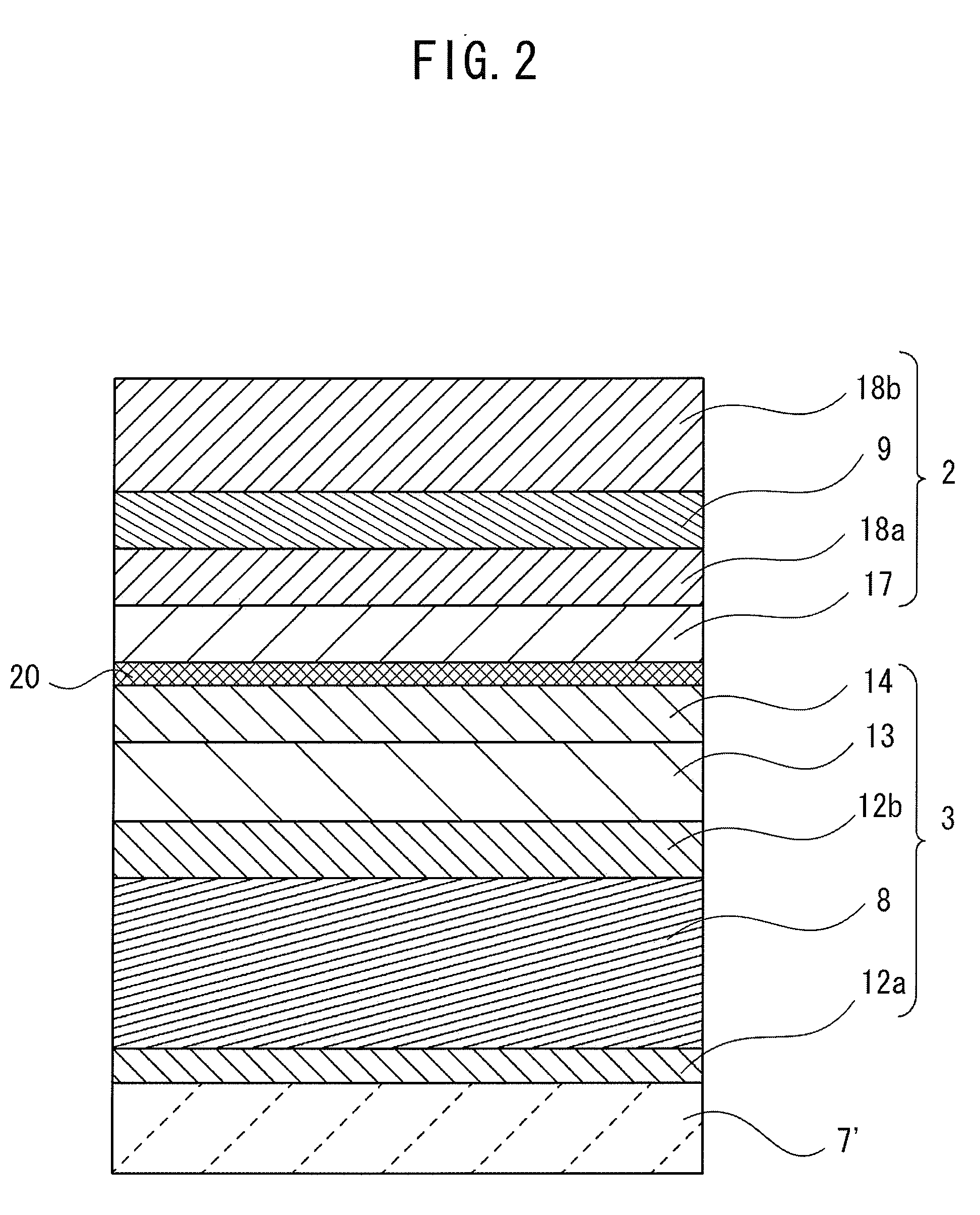
[0059]“Db” denotes the thickness of a first conductive layer 8, and “Dt” denotes the thickness of a second conductive layer 9. The ratio α between the sheet resistivities of an upper-barrier layer and a lower-barrier layer does not fluctuate even when the film formation rate of the respective conductive layers 8 and 9 has fluctuated. By utilizing this fact, the ratio α can be calculated as α=Rb / Rt≈Rbo / Rto≈Db / Dt by using the thickness ratio between the respective conductive layers 8 and 9.

[0060]Incidentally, both the units of the thicknesses Db and Dt are [m] in the SI unit system, but the thicknesses are on the order of several nm in this embodiment.

third embodiment

[0061]Next, a method for measuring the sheet resistance of a magneto-resistance effect element, will be described.

[0062]The third embodiment is the same as in the first embodiment in that establishing is performed after a first sheet resistivity Rt and a second sheet resistivity Rb have been obtained beforehand. In the third embodiment, however, each of the sheet resistivities Rt and Rb is acquired by performing the prior-art CIPT method a plurality of times (several tens times-several hundred times) and calculating the average value of obtained values.

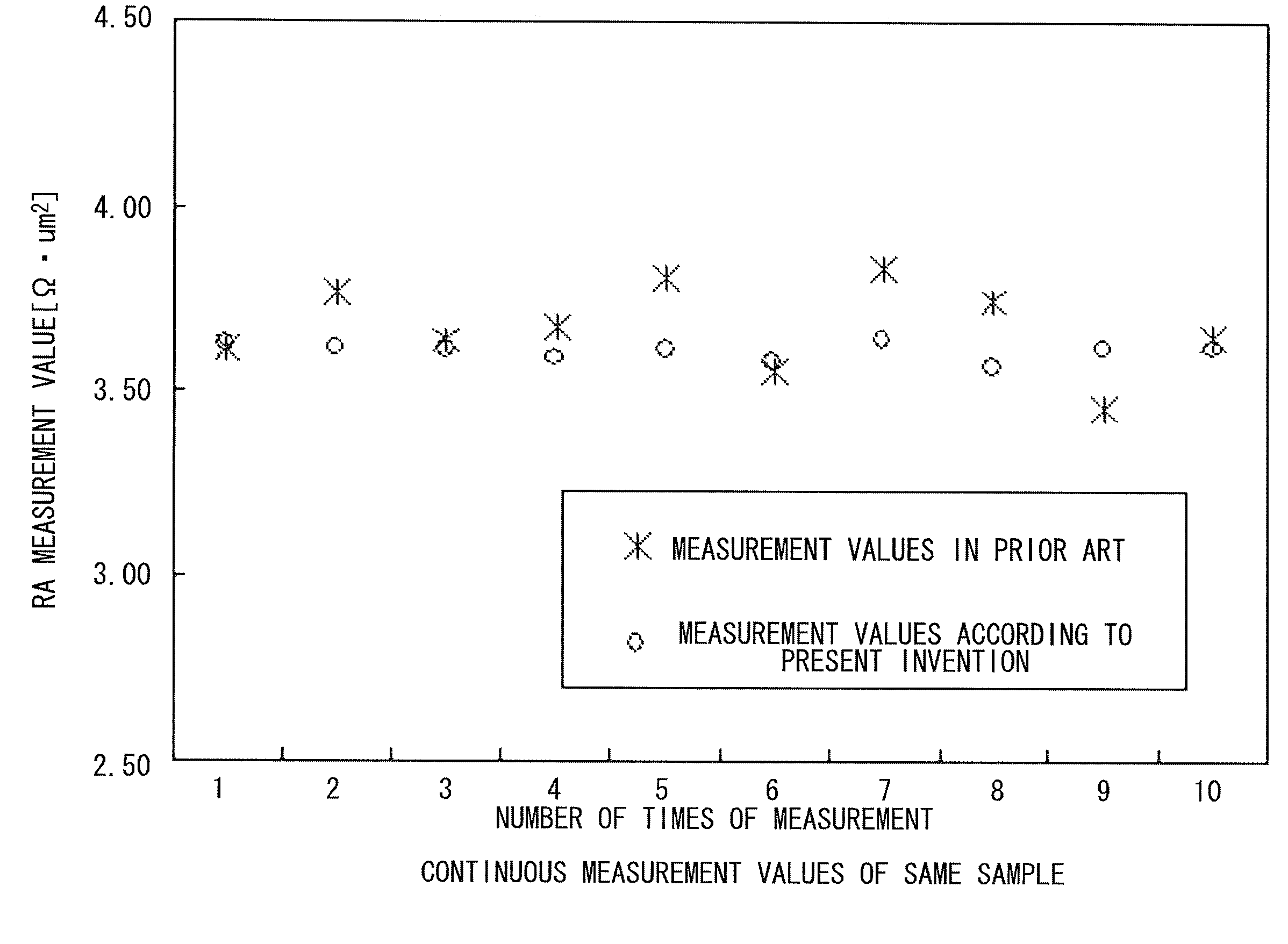
[0063]As described above, in accordance with the method for measuring the area resistance of the magneto-resistance effect element, according to this embodiment, the establishing with one variable becomes possible, whereby a measurement value (RA value) of high precision can be easily acquired. As a result, the characteristics of a TMR film can be evaluated with high precision on the basis of the RA value. Further, it is permitted to...


PUM


Abstract

A method for measuring an area resistance of a magneto-resistance effect element which includes an upper-barrier layer having a first sheet resistivity Rt, a barrier layer, and a lower-barrier layer having a second sheet resistivity Rb, includes a resistance measurement step, a sheet resistivity measurement step and a establishing step. The resistance measurement step is the step of measuring a resistance R of the magneto-resistance effect element by using predetermined terminals. The sheet resistivity measurement step measures the first sheet resistivity Rt and the second sheet resistivity Rb. The establishing step determines the area resistance RA of the magneto-resistance effect element using the first sheet resistivity Rt, the second sheet resistivity Rb, the resistance R and the intervals among the predetermined terminals.

Description

CROSS-REFERENCE TO RELATED APPLICATION[0001]This application is based upon and claims the benefit of priority of prior Japanese Patent Application No. 2007-298828, filed on Nov. 19, 2007, the entire contents of which are incorporated herein by reference.BACKGROUND[0002]1. Field[0003]An aspect of the invention is related to a method for measuring the area resistance of a magneto-resistance effect element which includes an upper-barrier layer having a first sheet resistivity, a barrier layer, and a lower-barrier layer having a second sheet resistivity.[0004]2. Description of the Related Art[0005]A TMR element is mentioned as an example of a magneto-resistance effect element which includes an upper-barrier layer, a barrier layer, and a lower-barrier layer.[0006]Regarding a TMR (Tunneling Magneto-Resistance) effect, a first report was made in 1975. Thereafter, it was reported in 1995 that a junction film employing aluminum oxide (AlO) for the barrier layer could attain a very large MR r...

Claims


Application Information

Patent Timeline
Patent Type & Authority Applications(United States)
IPC IPC(8): G01R27/02
CPCB82Y25/00H01L43/08G01R33/098G01R33/093H10N50/10
Inventor HAMADA, YUSUKEKAWAI, KENICHI
Owner FUJITSU LTD
Why Eureka
Try Eureka