Display

a technology of display and control film, applied in the field of display, can solve the problems of affecting the appearance of the display, and unable to enable the privacy function to be switched off in the prior art light control film, etc., and achieves the effects of simple electrode pattern, simple implementation, and easy manufacturing

Inactive Publication Date: 2009-05-21
SHARP KK
View PDF17 Cites 66 Cited by
  • Summary
  • Abstract
  • Description
  • Claims
  • Application Information

AI Technical Summary

Benefits of technology

[0059]It is thus possible to provide a display whose viewing angle may be switched, for example, between a wide view mode and a narrow or private view mode. The first liquid crystal device may be used with a display device which can be of any suitable type and whose operation need not be changed in order to provide the wide and narrow view modes.
[0060]Such a display may be used, for example, in desktop monitors, mobile telephones and personal digital assistants (PDAs). Such an arrangement is simple to implement and may be manufactured by well-known and established manufacturing techniques. In some preferred embodiments of the present invention, the first liquid crystal device does not require any electrode patterning or internal structure, for example, to define pixels. If the first liquid crystal device has a single liquid crystal region for switching the viewing angle range across the whole of the display device, a very simple electrode pattern may be used and is easy to manufacture. Although the display may be switched between the first and second viewing angle ranges, the viewing angle may be varied continuously or in steps by, for example, applying the appropriate drive voltages to the first liquid crystal device.

Problems solved by technology

However, light traveling at large angles relative to the plane of the opaque layers is incident on one of the opaque layers and is absorbed.
However, none of the prior art light control films enables the privacy function to be switched off to allow viewing from a wide range of angles.
This method has the disadvantage that it contains moving parts which may fail or be damaged in use, and which add bulk to the display.
They have the disadvantage that the light control film always absorbs a significant fraction of the light incident upon it, whether the display is in public mode or private mode.
The display is therefore inherently inefficient in its use of light.
Another disadvantage of these devices relates to their power consumption.
This is a disadvantage for mobile devices which are used for most of the time in the public mode and which have limited battery power.
One significant disadvantage of this device is the difficulty and expense of manufacturing liquid crystal cells with an appropriate shape.
A second disadvantage is that, in the private mode, a ray of light may enter at an angle such that it passes first through the transparent material and then through part of a liquid crystal cell.
Such a ray will not be completely absorbed by the liquid crystal cell and this may reduce the privacy of the device.
This checkerboard pattern is confusing for the viewer and degrades the quality of the image seen from an angle well away from the normal direction.
This does have the disadvantage that an additional LC panel and an additional polarizer are required.
While the display of Japanese Patent Application No. 9-105958 can provide a narrow display mode, it is difficult to switch the view angle control device to give a wide display mode.
However, this requires heating the liquid crystal material to a temperature at which it becomes isotropic, and this is undesirable.
However, this requires switching the liquid crystal molecules between a vertical alignment and a horizontal alignment, and this is very hard to do in practice.
This approach has the disadvantage that it cannot obtain a good private viewing mode with newer liquid crystal materials that have grey level curves with a much reduced dependence on viewing angle.

Method used


Image

  • Display
  • Display
  • Display

Examples


Embodiment Construction

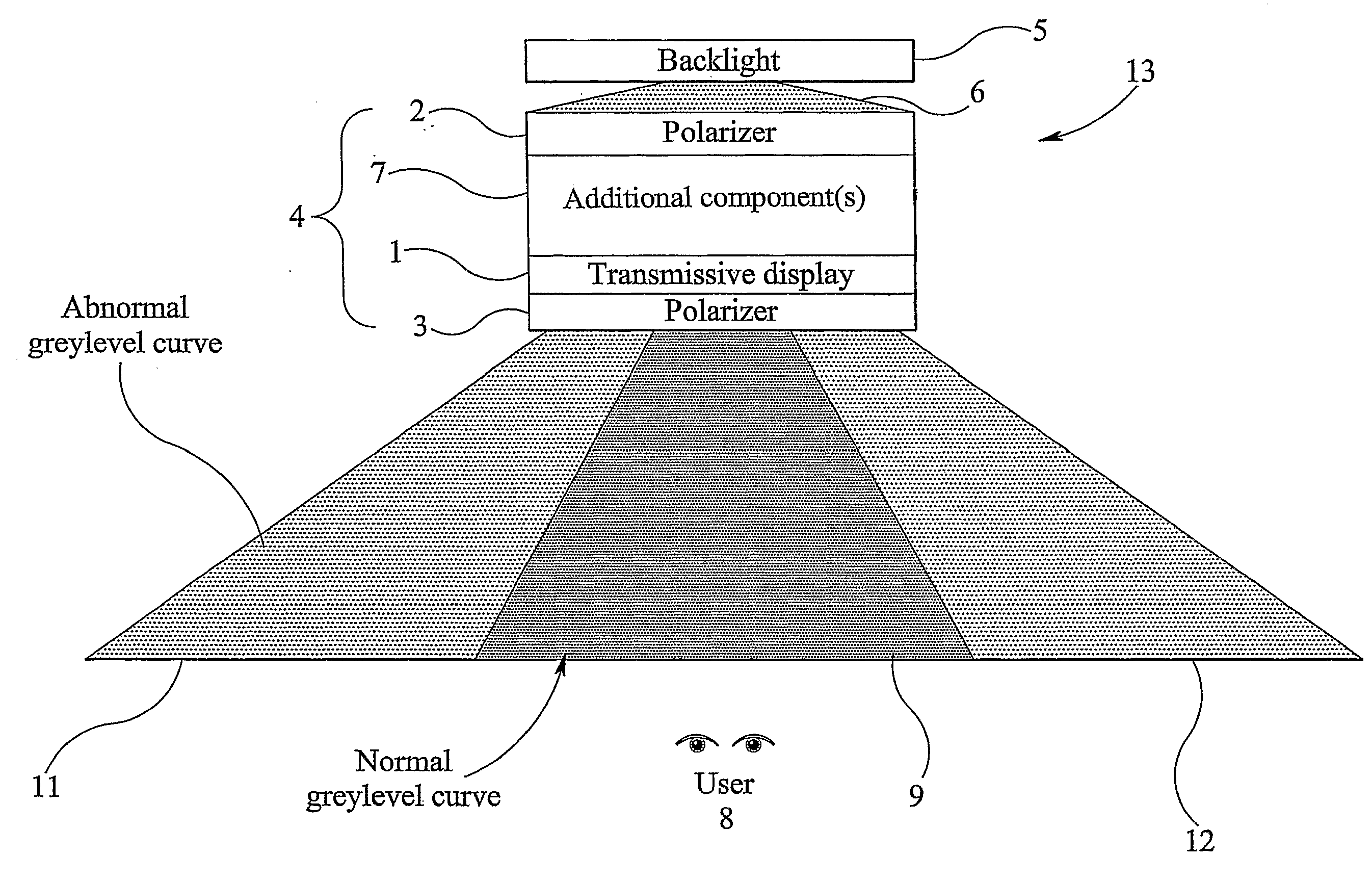
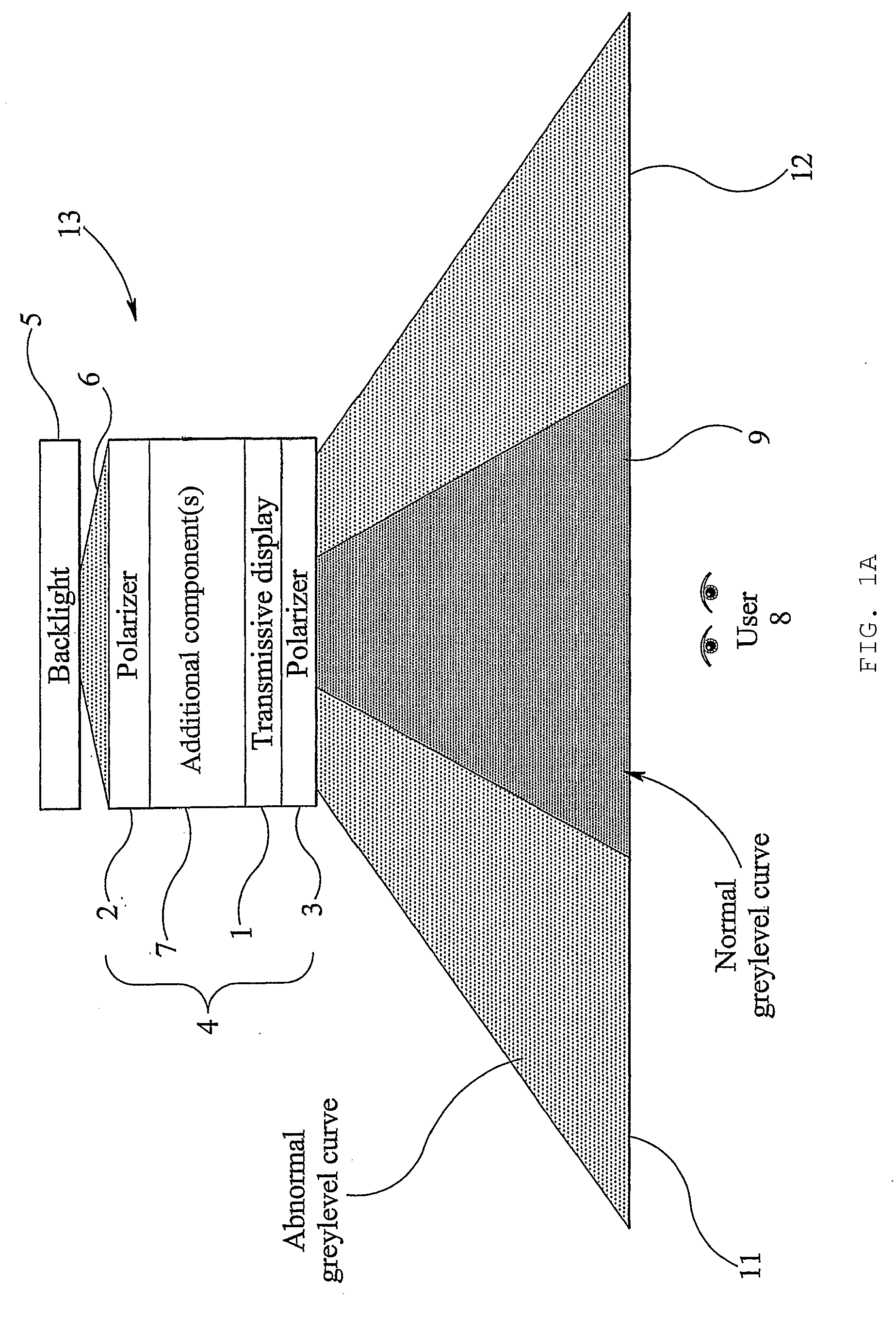
[0085]FIG. 1A is a schematic plan sectional view of a display 13 according to a preferred embodiment of the present invention. The display preferably includes a transmissive image display layer 1 which can be driven to display a desired image. The image display layer 1 may be of a conventional type, which does not require any change in order to provide a display having a wide view mode and a narrow view mode. For example, the image display layer 1 may be a liquid crystal layer, and in particular may include a thin film transistor (TFT) liquid crystal panel that provides a pixelated full color or monochrome display in response to image data supplied to the display. However, any suitable display layer may be used.

[0086]The image display layer 1 is disposed between an entrance polarizer 2 and an exit polarizer 3. The polarizers 2, 3 and the image display layer 1 together constitute an image display device 4.

[0087]The display is illuminated by a backlight 5 which emits light with reason...


PUM

PropertyMeasurementUnit
viewing angleaaaaaaaaaa
voltageaaaaaaaaaa
voltageaaaaaaaaaa

Abstract

A display includes a display device having a first polarizer and a second polarizer or a reflector, and a display layer disposed between the first polarizer and the second polarizer or the reflector. A liquid crystal layer is disposed between the display layer and one of the first polarizer and the second polarizer or reflector. The liquid crystal molecules of at least one region of the liquid crystal layer are switchable between a first state in which the display has a first display mode with a first viewing angle range and a second state in which the display has a second display mode having a second viewing angle range smaller than the first viewing angle range. In the second state, liquid crystal molecules of the at least one region are tilted with respect to the normal axis of the display over at least a portion of the thickness of the liquid crystal layer, and lie substantially parallel to a plane defined by the normal axis of the display and the transmission axis or absorption axis of the first polarizer or one of the first and second polarizers.

Description

BACKGROUND OF THE INVENTION[0001]1. Field of the Invention[0002]The present invention relates to a display in which the angular output range of light is controllable, so that the display can be switched between a wide angle viewing mode and a narrow angle viewing mode.[0003]2. Description of the Related Art[0004]Electronic display devices such as, for example, monitors used with computers and screens built in to mobile telephones and other portable information devices, are usually designed to have as wide a viewing angle as possible, so that an image displayed by the device can be seen from many different viewing positions. However, there are some situations where it is desirable for an image displayed by a device to be visible from only a narrow range of viewing angles. For example, a person using a portable computer in a crowded train might want the display screen of the computer to have a small viewing angle so that a document displayed on the computer screen cannot be read by ot...

Claims


Application Information

Patent Timeline
Patent Type & Authority Applications(United States)
IPC IPC(8): G02F1/1335G02F1/133G02F1/1337G02F1/1347
CPCG02F1/1323G02F2001/133761G02F1/13471G02F1/133761
Inventor KEAN, DIANA ULRICHCARVER, ANTHONY JOHNGASS, PAUL ANTHONYSTEVENSON, HEATHER ANNWALTON, EMMA JAYNE
Owner SHARP KK
Why Eureka
Try Eureka