Drive Unit For A Laboratory Centrifuge

Inactive Publication Date: 2009-05-21
HANNING ELECTRO WERKE GMBH & CO KG
View PDF9 Cites 9 Cited by
  • Summary
  • Abstract
  • Description
  • Claims
  • Application Information

AI Technical Summary

Benefits of technology

[0013]The motor has a stator assembly, and insulator plates for the stator end windings are provided on both sides of said stator assembly. The flattish end windings may be surrounded by insulating pieces, to facilitate a particularly compact structure of the motor, wherewith the separation distances of the insulating pieces can be kept small. Also, the insulating pieces allow electrical safety requirements to be satisfied, which require a safe and reliable separation between the motor and the contactable parts of the centrifuge. The insulation plates and insulating pieces comply with a requirement of double insulation between the stator winding and the rotor, in particular between the stator winding and the drive shaft assembly.
[0014]For particularly good damping of vibrations and suppression of wobbling, the spring stabilizer is comprised of an outer ring which is lodged against the hollow shaft and an inner ring which is lodged against the inner shaft. Thus, one or more spring elements are disposed, e.g. rotationally symmetrically around the axis. The inner ring may surround the inner shaft in a close fit, and may be in for

Problems solved by technology

The configuration illustrated is somewhat costly, due to the configuration of the special electric motor.
However, the operating apparatus has a physically very long construction and is unsuitable for small centrifuges.
In addition, the elastic bearings cause “walk-th

Method used


Image

  • Drive Unit For A Laboratory Centrifuge
  • Drive Unit For A Laboratory Centrifuge
  • Drive Unit For A Laboratory Centrifuge

Examples


Example

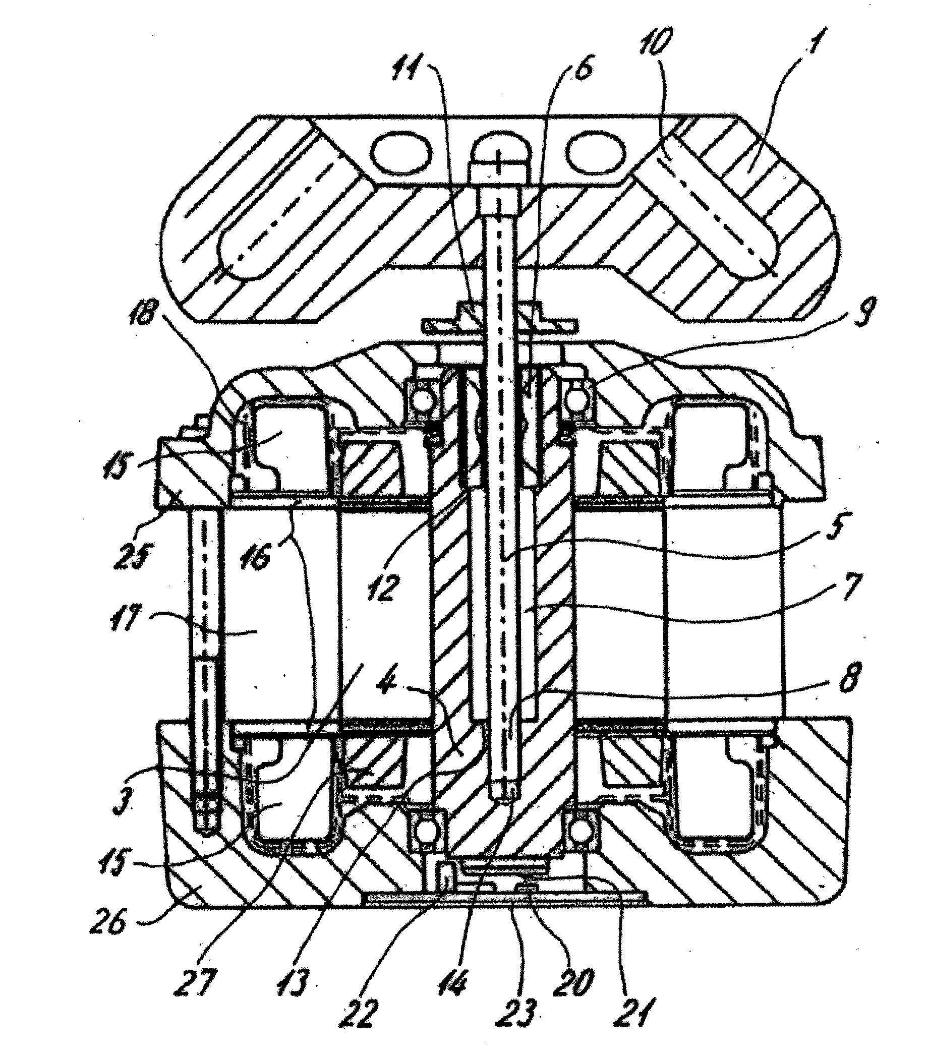
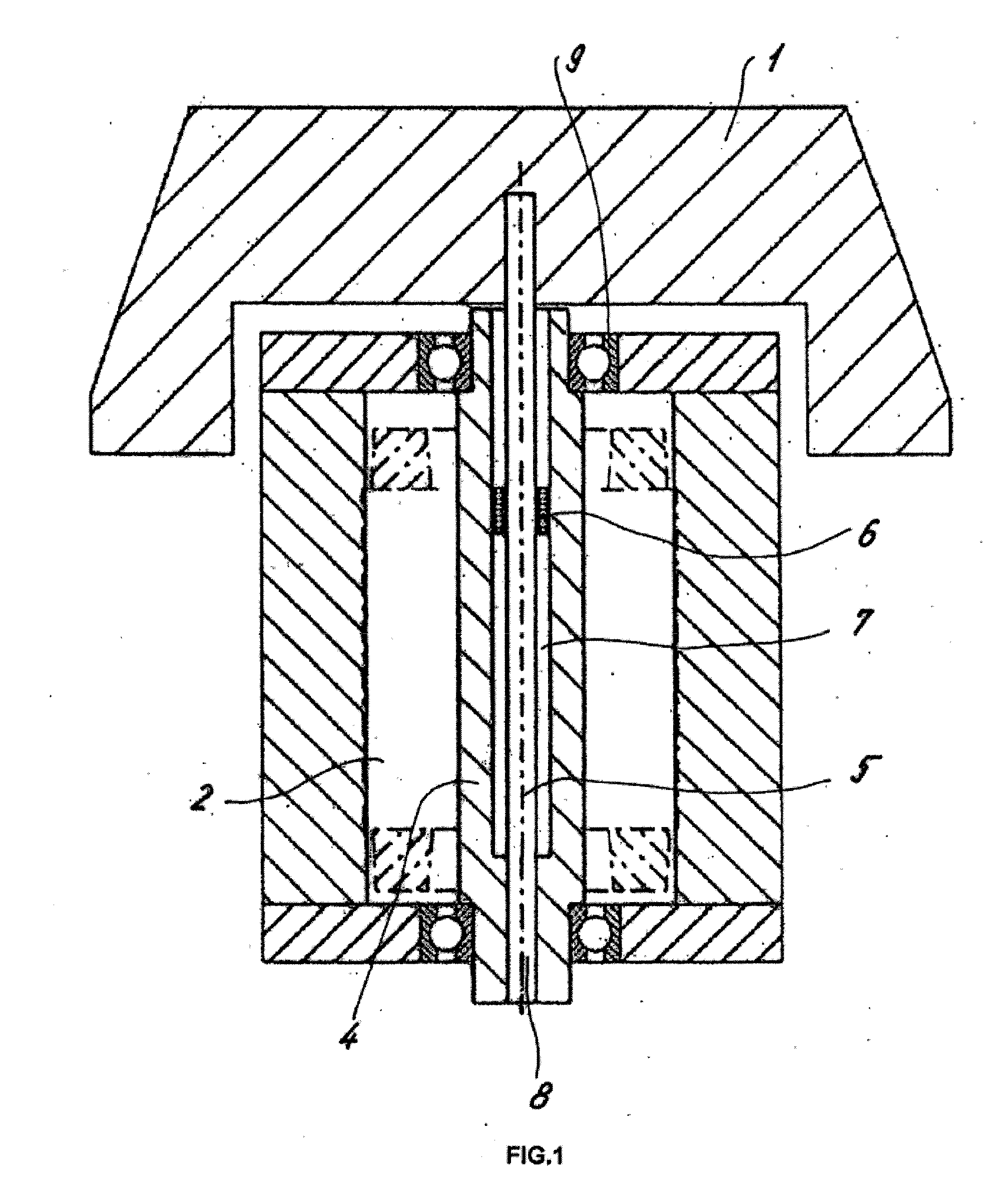
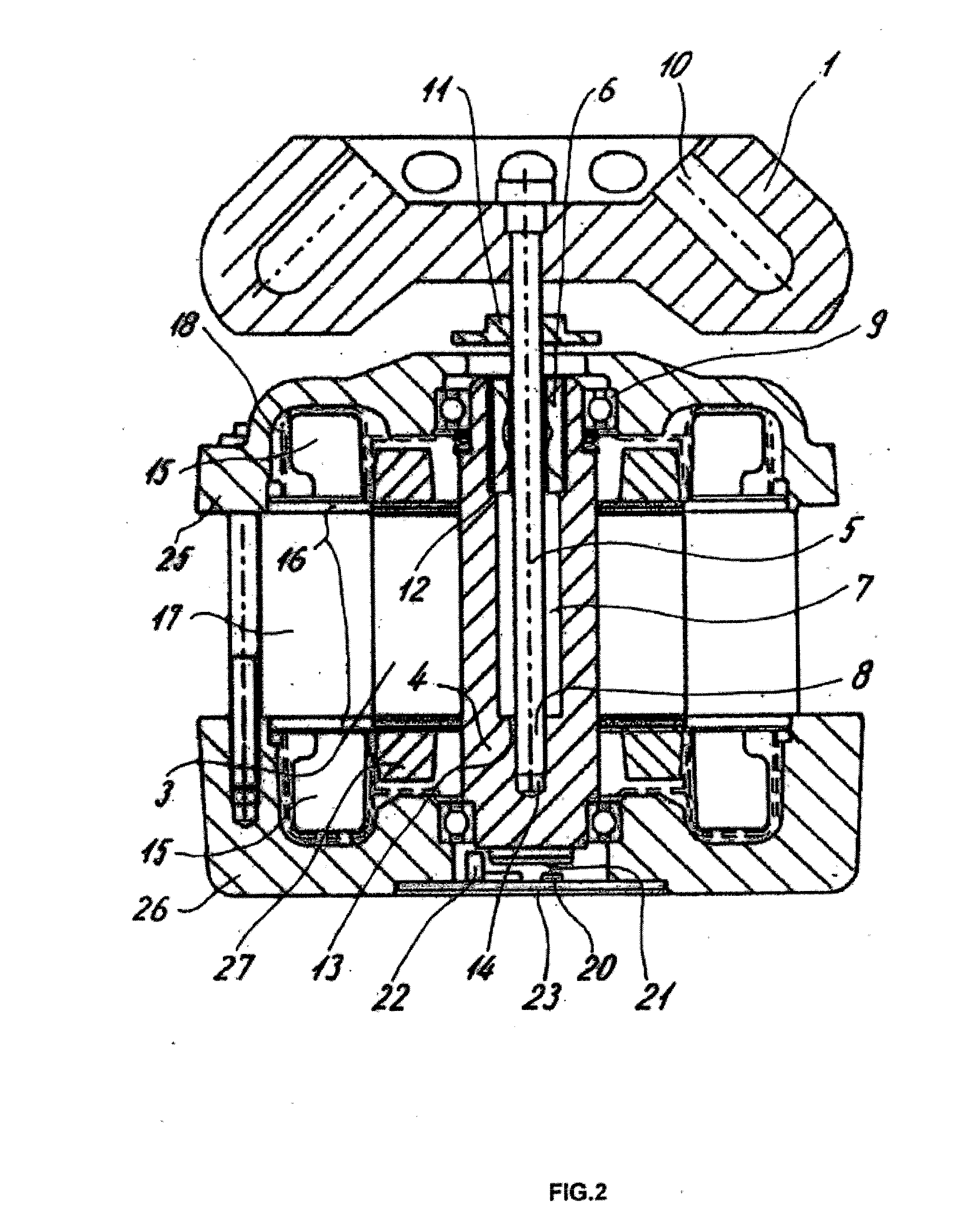
[0022]A laboratory centrifuge comprises a centrifuge rotor 1 in which samples can be disposed. The centrifuge rotor 1 is driven by a motor 2 which is shown only schematically in FIG. 1, which motor is disposed in a housing 3, shown in FIG. 2. The motor 2 drives a hollow shaft 4 which accommodates and holds inside it an inner shaft 5 of a lesser diameter. One end region 8 of the shaft 5 is disposed in a press fit inside the hollow shaft 4, and the opposite end of inner shaft 5 carries the centrifuge rotor 1.

[0023]The inner shaft 5 is oscillatably or cantileverly mounted between the centrifuge rotor 1 and the end region 8. A gap 7 is provided between the inner wall of the hollow shaft 4 and the outer wall of the inner shaft 5. A spring stabilizer 6, stabilizer having spring properties, is disposed in the gap 7. The stabilizer 6 springingly absorbs vibrations resulting from nonuniform loading of the centrifuge rotor 1, and stabilizes wobbling movements.

[0024]The drive unit of FIG. 1 is...


PUM


Abstract

A drive unit for a laboratory centrifuge, comprising a motor via which a centrifuge rotor that is attached to an inner shaft can be rotated. The motor drives a hollow shaft inside which the inner shaft that is attached in the centrifuge rotor is accommodated at least in part and is mounted to as to be able to oscillate. A spring stabilizer is disposed in the hollow shaft and around the inner shaft, whereby the drive unit is provided with a compact design while vibrations and noise are effectively reduced.

Description

BACKGROUND AND SUMMARY[0001]The present invention relates to a drive unit for a laboratory centrifuge, comprised of a motor by which a centrifuge rotor attached to a shaft is rotated.[0002]EP 867226 A2 discloses a laboratory centrifuge in which a rotor is spring-loadedly mounted via a shaft. The shaft and bearing is connected to the stator via four spring elements. The spring elements are intended to avoid vibration of the stator of the electric motor. The configuration illustrated is somewhat costly, due to the configuration of the special electric motor.[0003]DE 10038060 A1 discloses a centrifuge with an imbalance compensation device. A shaft carries a centrifuge rotor on one end, and the shaft has compensating rings which support it at a plurality of locations. The elastic bearing system described allows noises, vibrations, and a certain amount of imbalances to be compensated. However, the operating apparatus has a physically very long construction and is unsuitable for small cen...

Claims


Application Information

Patent Timeline
IPC IPC(8): B04B9/00
CPCB04B9/04H02K7/16B04B9/12
Inventor SOETEBIER, ERICH R.RAUSKOLB, RUDIGER
Owner HANNING ELECTRO WERKE GMBH & CO KG
Why Eureka
Try Eureka