Method and System for Deployed Shielding Against Ballistic Threats

a technology of ballistic threats and shielding methods, applied in shields, reactive armour, instruments, etc., can solve the problems of inability to protect the unit from direct hits of bombs, missiles, rockets, etc., and the survival and operability of the unit is affected, and traditional heavy-duty protective barrier shielding techniques are often not practical

Inactive Publication Date: 2009-05-21
ELTA SYST LTD
View PDF0 Cites 8 Cited by
  • Summary
  • Abstract
  • Description
  • Claims
  • Application Information

AI Technical Summary

Benefits of technology

[0015]The present invention is effective for protecting mainly against nearby impact debris and also partially direct hits, such as bullets.

Problems solved by technology

Units positioned in a field of multi-directional threats, such as in the battlefield, are frequently under the dangers of direct hits of bombs, rockets, missiles, incoming weapons fire and the like.
The indirect effects of shrapnel, debris and fireballs as a result of a nearby hit or explosion of said multi-directional threats can be equally detrimental to the survival and operability of the unit.
Since units such as radar sensor units require a large field of visibility, traditional heavy-duty protective barrier shielding techniques are often not practical.
Shielding a radar sensor unit with surrounding concrete and steel walls will most likely render the unit useless, for such walls block the line of sight of the radar sensor.
Various RF transparent materials are known to be used in protective radomes fitted around the radar unit's antenna, but these provide limited protection from environmental conditions and do not provide any solution against ballistic and blast effects.
However these methods of protection render the protected unit inoperable for the duration of the protection and once used and thereafter removed the shielding device cannot be repositioned against later detected threats.

Method used


Image

  • Method and System for Deployed Shielding Against Ballistic Threats
  • Method and System for Deployed Shielding Against Ballistic Threats
  • Method and System for Deployed Shielding Against Ballistic Threats

Examples


Embodiment Construction

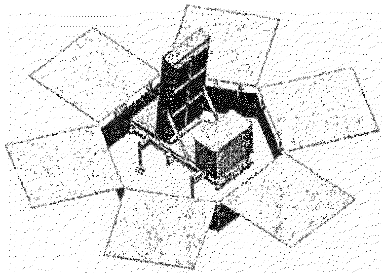
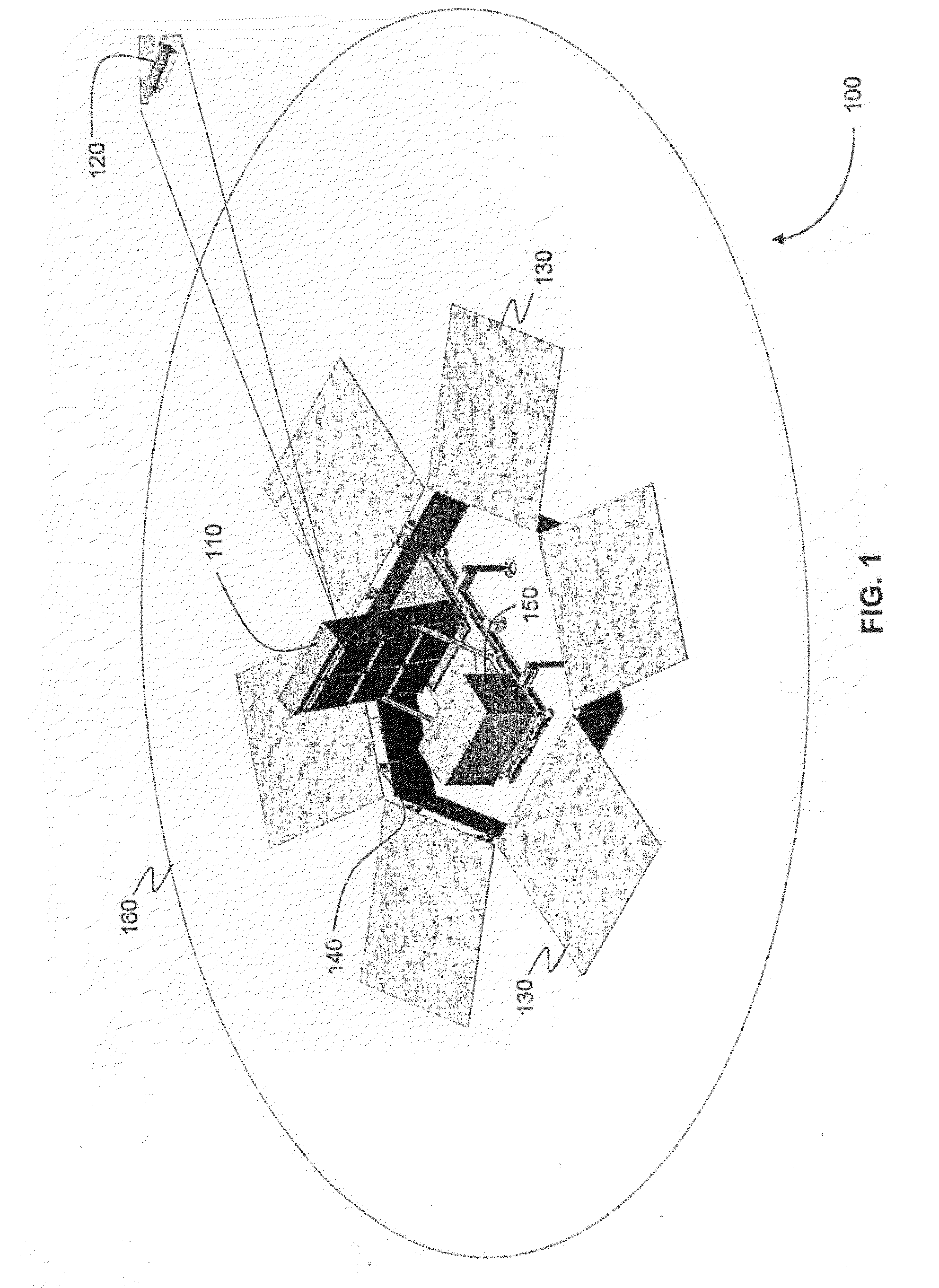
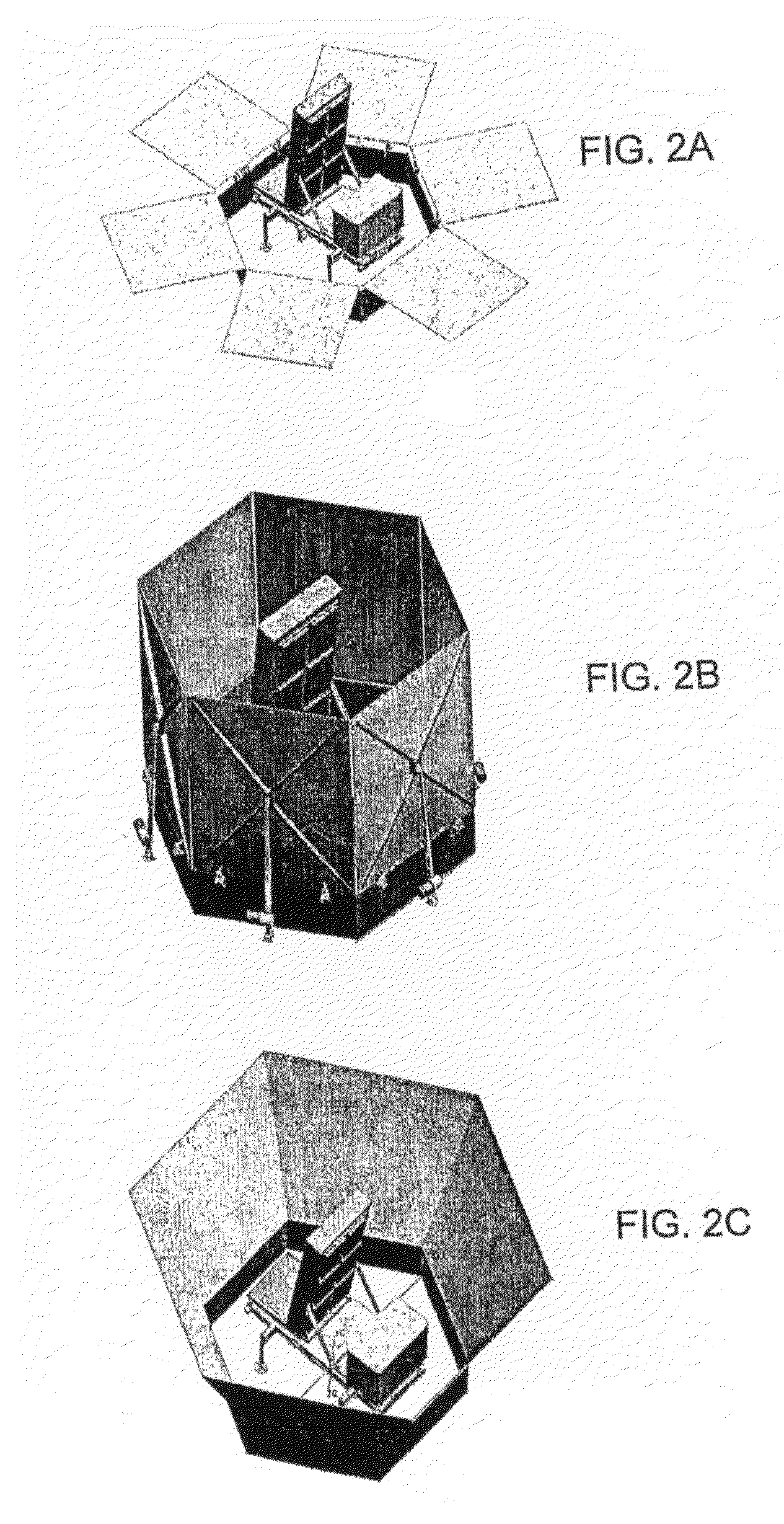
[0022]FIG. 1 is a perspective view showing a system 100 in its regular operational state for protecting a radar unit 110 (constituting a sensor unit) against attack by potential aerial targets, such as the target 120. The system 100 includes a plurality of deployable shields 130 (constituting primary shields) that may be installed in the field so as to surround the radar unit 110 and, when deployed by respective actuators shown schematically as 140 controlled by a control unit 150, shield the radar unit 110 against incoming ballistic objects. FIG. 2a shows the shields in a stowed position whereby the radar unit is unprotected. FIG. 2b shows the shields in a fully erect position whereby the circumference of the radar unit is protected. FIG. 2c shows the shields in a partially erected position, which offers substantial protection to the radar unit, while allowing the shields to be returned more quickly to their first stowed position once no more threats are detected.

[0023]The shields ...


PUM


Abstract

A system shields field-deployable equipment from effects of nearby multi-directional threats, the equipment including or being mounted in association with a sensor unit having at least one sensor operable to detect the motion of an in-flight projectile and to generate a nearby impact point determination. Shields are mounted in spaced relationship with the equipment and adapted to be moved from first position wherein the equipment is fully exposed to a second position wherein the equipment is at least partially shielded, and a control unit is coupled to the shields and is responsive to detection of an in-flight projectile prior to nearby impact for moving at least one of the shields from the first position to the second position.

Description

FIELD OF THE INVENTION[0001]This invention relates to systems and methods which provide ballistic shielding. This invention relates more particularly to shielding a unit having sensor capabilities from ballistic and blast effects caused by incoming threats.BACKGROUND OF THE INVENTION[0002]Units positioned in a field of multi-directional threats, such as in the battlefield, are frequently under the dangers of direct hits of bombs, rockets, missiles, incoming weapons fire and the like. The indirect effects of shrapnel, debris and fireballs as a result of a nearby hit or explosion of said multi-directional threats can be equally detrimental to the survival and operability of the unit.[0003]To address such threats numerous methods and systems are known to be used for blast mitigation purposes. Examples include bullet-proof casings, concrete and steel building structures, armor plates, and others. The particular avenue taken depends upon factors such as degree and likelihood of threat, r...

Claims


Application Information

Patent Timeline
Patent Type & Authority Applications(United States)
IPC IPC(8): G05D1/12F41H5/06
CPCF41H11/02F41H5/007
Inventor LESHEM, AVRAHAM
Owner ELTA SYST LTD
Why Eureka
Try Eureka