Clutch control system for transmission

Active Publication Date: 2009-05-21
HONDA MOTOR CO LTD
View PDF9 Cites 12 Cited by
  • Summary
  • Abstract
  • Description
  • Claims
  • Application Information

AI Technical Summary

Benefits of technology

[0019]According to an embodiment of the present invention, the clutch control system includes the control section for controlling the supply of hydraulic pressure to each of the hydraulic clutches switched from a disengagement state to an engagement state upon receiving a predetermined hydraulic pressure generated by a hydraulic pump wherein the transmission in which shifting to an adjacent gear step by operation of the switching the engagement state of the hydraulic clutches from one side to the other side. The input-output speed ratio detecting means is provided for detecting an input-output speed ratio of the transmission. The control section discontinues the switching operation of the clutches if an elapsed time from start of the switching operation reaches a predetermined time and the input-output speed ratio falls within a predetermined range corresponding to a gear step before shifting. Therefore, the clutch control system detects that a clutch that is to be switched from the engagement state to the disengagement state at the time of shifting remains in the engagement state on the basis of a value of the input-output speed ratio and can discontinue the switching operation of the clutches. Thus, it is possible to avoid the so-called clutch interlock in which two clutches are simultaneously engaged to put a load thereon. In addition, the clutch interlock can be avoided without the provision of a sensor or the like for detecting the hydraulic pressure of each clutch.
[0020]According to an embodiment of the present invention, the control section discontinues the switching operation by switching the other side clutch into the disengagement state. Therefore, the clutch interlock can quickly be avoided by the operation of stopping the supply of hydraulic pressure to the other side clutches.
[0021]According to an embodiment of the present invention, the clutch control system includes the warning means for warning that the switching operation is discontinued. Thus, it is possible for an occupant to quickly recognize any failure occurring in the driving passage for the hydraulic clutches and enables prompt response such as discontinuance of the operation or check and repair.
[0027]According to an embodiment of the present invention, the control section, if the rotational speed of the front wheel is greater than that of the rear wheel and the rotational speed difference exceeds a predetermined value, determines that the motorcycle is in a turning maneuver and prohibits the automatic gear shifting. Therefore, it is possible to detect the turning maneuver state using the characteristic of the motorcycle in which a difference in rotational speed between the front and rear wheels occurs during a turning maneuver and to prohibit the gear shifting during the turning maneuver. Thus, it is possible to enhance a feeling during the turning maneuver. In addition, since it can be determined that the motorcycle is in the turning maneuver by detecting the rotational speeds of the front and rear wheels without use of a transverse G sensor or the like, it is possible to suppress the increased number of component parts. Thus, an increase in the production costs and man-hours are reduced.
[0028]According to an embodiment of the present invention, the control section prohibits the automatic gear shifting if the rotational speed difference exceeds a predetermined value and the vehicle speed is below a predetermined value. Thus, by using the characteristic of the motorcycle in which during a turning maneuver with a small turning radius, the rotational speed difference between the front and rear wheels tends to increase and vehicle speed tends to lower, the control section can surely detect such a turning state and can prohibit the automatic gear shifting of a transmission.

Problems solved by technology

However, the twin clutch type transmission as mentioned above is not provided with a shift valve for switching the oil passages per se.
Therefore, when the supply destination of hydraulic pressure is switched from one of the clutches to the other by the clutch switching operation, the hydraulic pressure of the one of the clutches may not be lowered due to any cause.
In such a case, there is a possibility that the shifting operation may appropriately not be completed.
Therefore, it does not make consideration of the problem specific to the twin clutch type transmission having the configuration described above.

Method used


Image

  • Clutch control system for transmission
  • Clutch control system for transmission
  • Clutch control system for transmission

Examples


Embodiment Construction

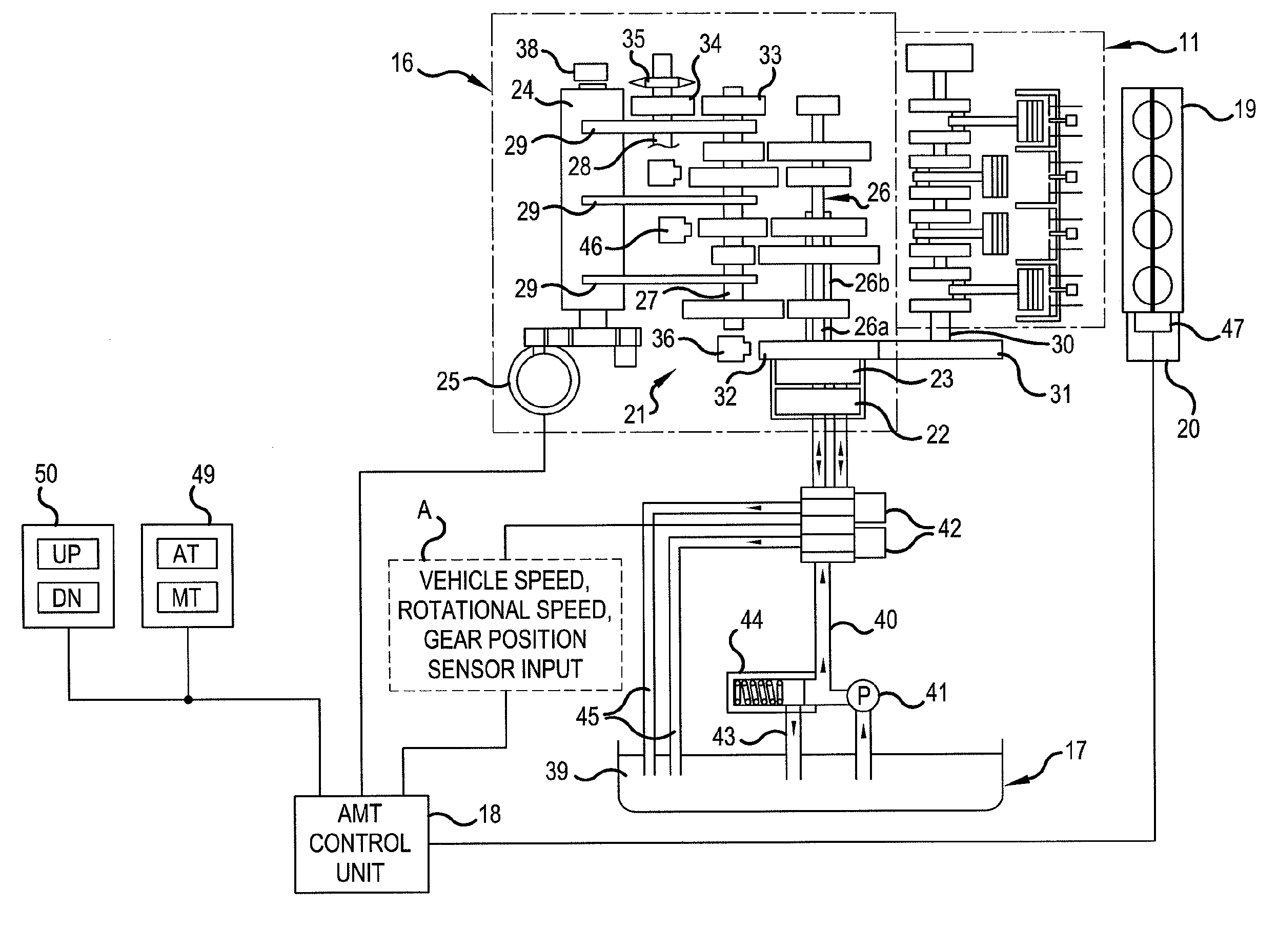
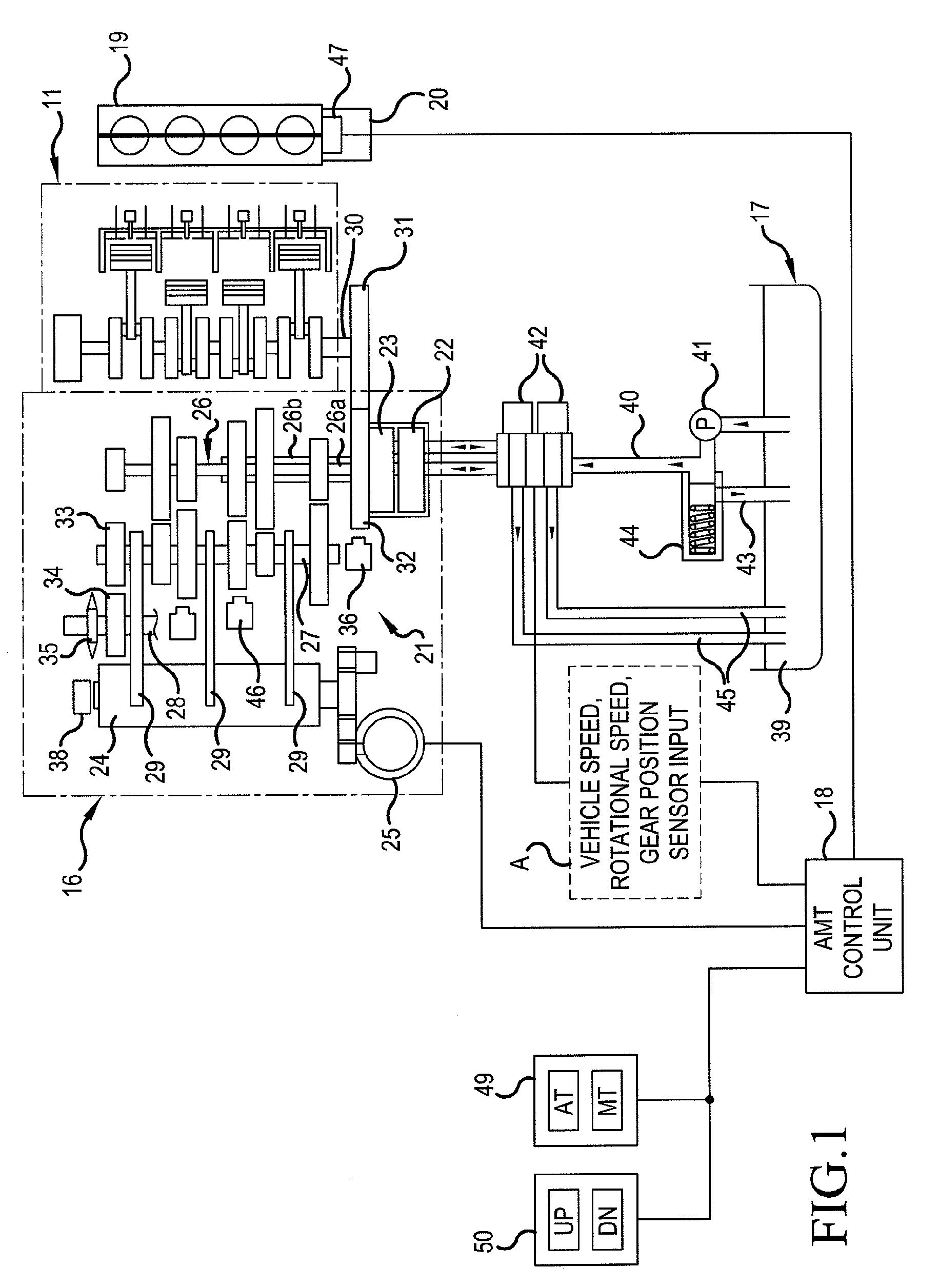
[0041]Preferred embodiments of the present invention will hereinafter be described in detail with reference to the drawings. FIG. 1 is a system diagram of an automated manual transmission (hereinafter referred to as an AMT) and an automatic transmission and its peripheral devices applied to a motorcycle. The AMT 16 coupled to an engine 11 is drivingly controlled by a clutch hydraulic device 17 and by an AMT control unit 18 as a speed-change control device. The engine 11 includes a throttle-by-wire type throttle body 19, which is equipped with a throttle opening-closing motor 20.

[0042]The AMT 16 includes a multi-step transmission gear 21, a first clutch 22, a second clutch 23, a shift drum 24, and a shift control motor 25 for turning the shift drum 24. A large number of gears constituting the transmission gear 21 are joined to or loosely fitted to a main shaft 26, to a counter shaft 27, and to a speed-change gear output shaft 28. The main shaft 26 is composed of an inner main shaft 2...


PUM


Abstract

A clutch control system for a transmission for detecting if hydraulic control during shifting is not executed. A first clutch and a second clutch are switched from a disengagement state to an engagement state by receiving a predetermined pressure generated by a hydraulic pump. A transmission executes shifting to an adjacent gear step by operation of switching the engagement state of the first clutch and of the second clutch from one side to the other side. If an elapse time t from the start of clutch switching operation reaches a predetermined time and an input-output speed ratio which is a ratio between engine speed and counter shaft rotational number falls within a predetermined range corresponding to a gear step before shifting, the transmission control unit discontinues the clutch switching operation by stopping the supply of hydraulic pressure to the other side clutch to bring it into the disengagement state.

Description

CROSS-REFERENCE TO RELATED APPLICATIONS[0001]The present application claims priority under 35 USC 119 to Japanese Patent Application No. 2007-310435 filed on Nov. 30, 2007 and Japanese Patent Application No. 2007-310585 filed on Nov. 21, 2007 the entire contents of which are hereby incorporated by reference.BACKGROUND OF THE INVENTION[0002]1. Field of the Invention[0003]The present invention relates generally to a clutch control system for a transmission. More particularly, to a clutch control system for a transmission that can detect the fact that hydraulic control during shifting is not executed as previously planned by detecting an input-output speed ratio of the transmission to appropriately deal with such an event. In addition, the present invention generally relates to gear shift control apparatuses for a motorcycle. More particularly, to a gear shift control apparatus that detects the turning state of the vehicle based on a difference in rotational speed between front and rea...

Claims


Application Information

Patent Timeline
IPC IPC(8): B60W10/10G06F17/00F16H59/04F16H61/12
CPCF16H59/70F16H61/12F16H2061/1264F16H2061/1244F16H2061/1204F16H2061/1208
Inventor KOJIMA, HIROYUKIIGUCHI, KAZUNARIMORIMITSU, KAZUMAOZEKI, TAKASHITSUKADA, YOSHIAKITAJIMA, SHIGERU
Owner HONDA MOTOR CO LTD
Why Eureka
Try Eureka