Virtual machine server sizing apparatus, virtual machine server sizing method, and virtual machine server sizing program

a virtual machine server and sizing technology, applied in the field of virtual machine server sizing apparatus, virtual machine server sizing method, and virtual machine server sizing program, can solve the problems of not considering the overhead caused, unable to calculate the system load, and unable to estimate the load of the system, so as to improve the accuracy of cpu load estimation under the virtualized environment

Inactive Publication Date: 2009-05-21
MITSUBISHI ELECTRIC CORP
View PDF19 Cites 31 Cited by
  • Summary
  • Abstract
  • Description
  • Claims
  • Application Information

AI Technical Summary

Benefits of technology

[0022]In a virtual machine server sizing apparatus pertinent to an aspect of the present invention, by a load managing unit, storing in a memory device a measured value of CPU load of a real server generated on each of the plurality of real servers and a measured value of I/O (Input/Output) load of a disk and/or a network generated on each of the plurality of real servers; by a load converting unit, previously storing in the memory device an I/O load conversion rate for obtaining an estimated value of CPU load of the virtual machine server generated by processing I/O by a virtual machine from a measured value of I/O load generated on each of the plurality of real servers, and calculating by a processing device an estimated value of CPU load of the virtu

Problems solved by technology

However, under virtualized environment, there are loads caused by the virtualization such as overhead caused by competition or scheduling of multiple servers operated on one physical machine, overhead caused by I/O (Input/Output) emulation generated at the time of accessing disks or network, etc.
However, this method cannot calculate the system load after the virtualization from statistical information obtained from servers to be integr

Method used


Image

  • Virtual machine server sizing apparatus, virtual machine server sizing method, and virtual machine server sizing program
  • Virtual machine server sizing apparatus, virtual machine server sizing method, and virtual machine server sizing program
  • Virtual machine server sizing apparatus, virtual machine server sizing method, and virtual machine server sizing program

Examples


embodiment 1

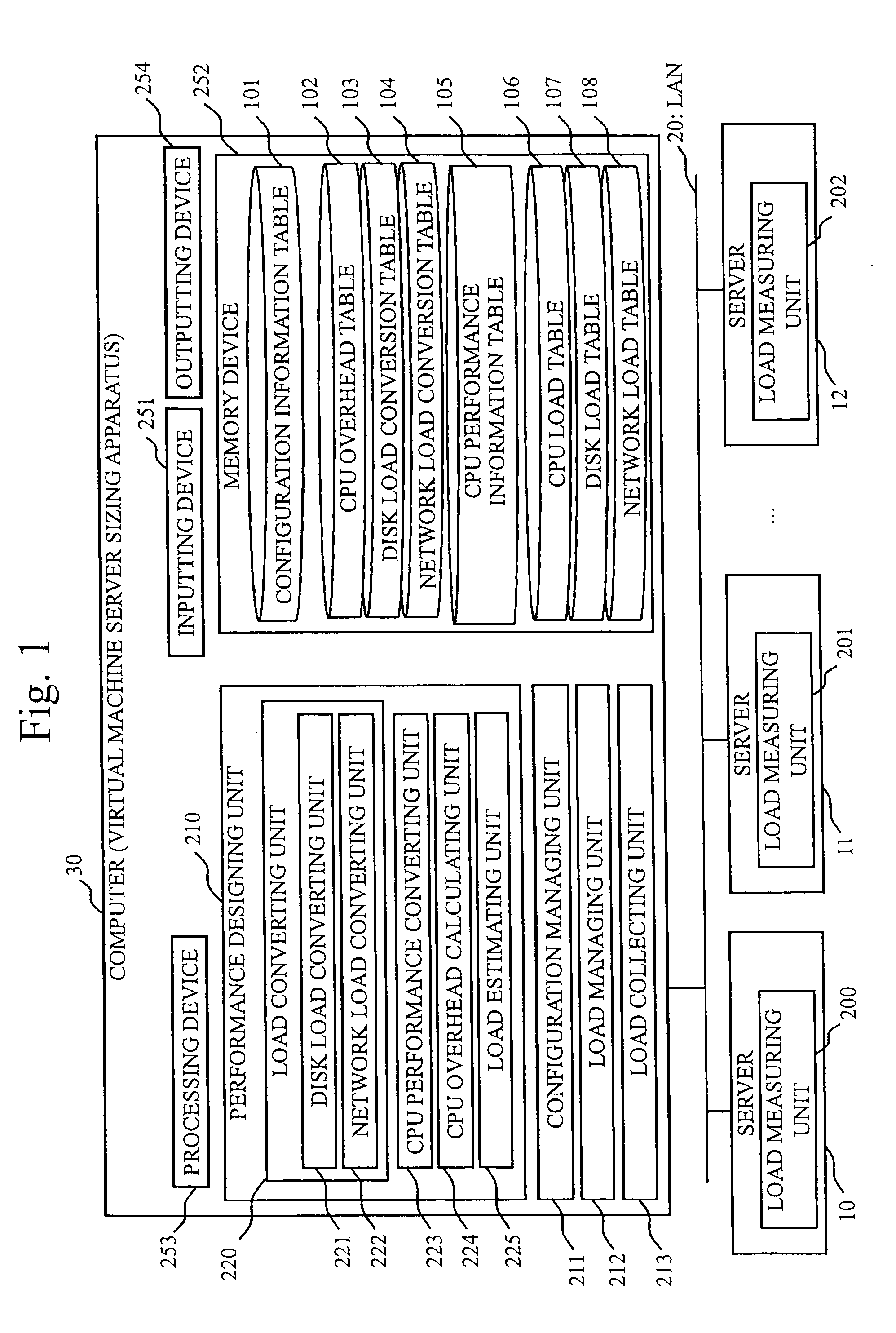
[0042]FIG. 1 is a block diagram showing a general configuration of a system according to the present embodiment.

[0043]In FIG. 1, servers 10 to 12 are non-virtual servers to be a target of server integration. A computer 30 is a terminal for operating a sizing function. The servers 10 to 12 and the computer 30 are connected via LAN (Local Area Network) 20. Each of the servers 10 to 12 is an example of a real server, and the computer 30 is an example of a virtual machine server sizing apparatus.

[0044]The servers 10 to 12 include load measuring units 200 to 202. Further, each of the servers 10 to 12 includes a HDD (Hard Disk Drive) and a NIC (Network Interface Card) as well as at least one CPU (Central Processing Unit) as hardware resource.

[0045]The load measuring units 200 to 202 measure system load of the servers 10 to 12, respectively, and output them as measured information. The system load means, for example, CPU load and I / O (Input / Output) load of disk or network. The CPU load mea...

embodiment 2

[0098]The present embodiment, in particular a difference from the first embodiment, will be explained.

[0099]In the first embodiment, at the CPU load calculating step, the disk load converting step, and the network load converting step, the maximum values of the CPU use rate, the number of disk I / Os, the disk band, the number of network I / Os, and the network band of the server to be integrated are obtained from the CPU load table 106, the disk load table 107, and the network load table 108, and these values are used for estimating the CPU load of each integrating server. However, it is also possible to use, for example, mean values, percentile values (e.g. 90 percentile values), etc. instead of the maximum values. Further, it is also possible to calculate and output multiple estimated values of the CPU load of each integrating server using multiple types of values among, for example, the maximum values, the minimum values, the percentile values, etc.

[0100]As mentioned above, accordin...

embodiment 3

[0101]The present embodiment, in particular a difference from the first embodiment, will be explained.

[0102]Configuration examples of the disk load conversion table 103, the network load conversion table 104, and the CPU overhead table 102 according to the present embodiment are shown in FIGS. 15, 16, and 17, respectively. The difference from the disk load conversion table 103, the network load conversion table 104, and the CPU overhead table 102 of the first embodiment shown in FIGS. 6, 7, and 9 is that a new column is added to each table to specify the virtualization technique.

[0103]The disk load conversion table 103 shown in FIG. 15 and the network load conversion table 104 shown in FIG. 16 store, for each kind of virtualization technique used for the benchmark test, the I / O number conversion rate, the band conversion rate, and the CPU performance value which are the results of the benchmark test. Similarly, the CPU overhead table 102 shown in FIG. 17 stores, for each kind of vir...


PUM


Abstract

It is an object to improve accuracy of estimation of CPU load by calculating the CPU load necessary for performing I/O emulation under the virtualized environment based on disk load and/or network load. In case of estimating CPU load of a server X which operates servers 10 to 12 as virtual servers, a CPU performance converting unit 223 obtains measured values of CPU load of the servers 10 to 12. A load converting unit 220 obtains an estimated value of the CPU load of the server X caused by I/Os of disks and/or network from disk load and/or network load of the servers 10 to 12. A CPU overhead calculating unit 224 obtains a coefficient showing CPU overhead caused by virtualization. A load estimating unit 225 estimates the CPU load of the server X using the above measured value, the above estimated value, and the above coefficient.

Description

BACKGROUND OF THE INVENTIONField of the Invention[0001]The present invention relates to a virtual machine server sizing apparatus, a virtual machine server sizing method, and a virtual machine server sizing program.LIST OF REFERENCES[0002][Patent Document 1] JP 2005-115653[0003][Non-Patent Document 1] Y. Ajiro and A. Tanaka, “Measuring Resource Management Overhead for Server Virtualization,” Research Report-System Evaluation, Information Processing Society of Japan, June 2006, Vol. 2006, pp. 17-22.DISCUSSION OF THE BACKGROUND[0004]In recent years, server integration to consolidate hundreds of servers in corporation into less number of high performance servers has drawn attention. It is an object to consolidate systems operated on multiple servers into one server using virtualization technique and to reduce operation and maintenance cost (for example, refer to Patent Document 1 and Non-Patent Document 1).[0005]In order to integrate servers using server virtualization technique, it is...

Claims


Application Information

Patent Timeline
IPC IPC(8): G06F9/455
CPCG06F11/3409G06F2201/815G06F11/3442
Inventor KANEKI, YUSUKE
Owner MITSUBISHI ELECTRIC CORP
Why Eureka
Try Eureka