Trailer Refrigeration System

a refrigeration system and trailer technology, applied in the field of trailer refrigeration systems, can solve the problems of engine speed and rotation speed of refrigerator engines being kept low, and engine size and weight increase, so as to reduce the size and weight of the electricity-generator engine (21). , the effect of optimal efficiency

Inactive Publication Date: 2009-05-28
DAIKIN IND LTD
View PDF4 Cites 60 Cited by
  • Summary
  • Abstract
  • Description
  • Claims
  • Application Information

AI Technical Summary

Benefits of technology

[0035]As described above, in accordance with the present invention, the electricity-generator engine (21), the electric compressor (31), and the fans (35), (36) can be controlled separately independently of one another, and it is no longer required that the electricity-generator engine (21) be driven in conjunction with the speed of rotation of the electric compressor (31) and the fans (35), (36). Accordingly, there is no need that the electricity-generator engine (21) be driven, for example, at low speed of rotation / high torque, thereby eliminating the need to increase the displacement of the electricity-generator engine (21) more than is necessary. As a result, it becomes possible to reduce the electricity-generator engine (21) in both size and weight.
[0036]Besides, it is possible to drive the electricity-generator engine (21) at a speed of rotation that provides optimal efficiency for the electricity-generator engine (21), regardless of the electric compressor (31) et cetera. As a result, it becomes possible to achieve the energy saving of the system.
[0037]In addition, in accordance with the seventh aspect of the present invention, it is possible to reduce the starting torque of the electricity-generator engine (21). Therefore, it becomes possible to reduce the quantity of electric power that the electricity generator (22) is required to generate, thereby making it possible to reduce the power required by the electricity-generator engine (21). As a result, it becomes possible to reduce the size and weight of the electricity-generator engine (21) to a further extent.
[0038]In addition, in accordance with the eighth aspect of the present invention, it is arranged such that the converter (23) can be, switchably from the electricity generator (22), connected to a commercial power supply source. As a result, for example, in the case where the refrigeration vehicle is stopped and remains parked for many hours, there is no need to drive the electricity-generator engine (21). As a result, it becomes possible to achieve the energy saving of the electricity-generator engine (21).
[0039]In addition, in accordance with the ninth to the fourteenth aspect of the present invention, it is possible to detect whether or not a malfunction is occurring in the electricity-generator engine (21) and the fan (35, 36)), e.g., whether or not they are about to malfunction. It is arranged such that upon the detection of such a malfunction, the load of the electric compressor (31) et cetera is reduced. This enables the electricity-generator engine (21) and the fan (35, 36) to operate for as long as possible until the time of replacement.

Problems solved by technology

The problem with this is that it is required that the speed of rotation of the refrigerator engine be kept low because of the constraint imposed by the allowable speed of rotation of the compressor.
However, this speed of rotation is extremely lower than the rated speed of rotation of the refrigerator engine.
This causes the problem that the engine grows in both size and weight.

Method used


Image

  • Trailer Refrigeration System
  • Trailer Refrigeration System
  • Trailer Refrigeration System

Examples


Embodiment Construction

[0067]In the following, an exemplary embodiment of the present invention will be described in detail with reference to the accompanying drawings.

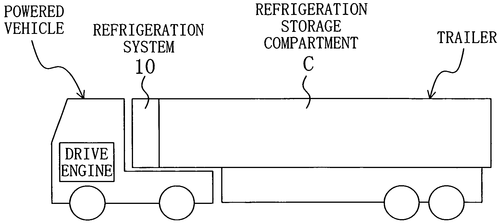
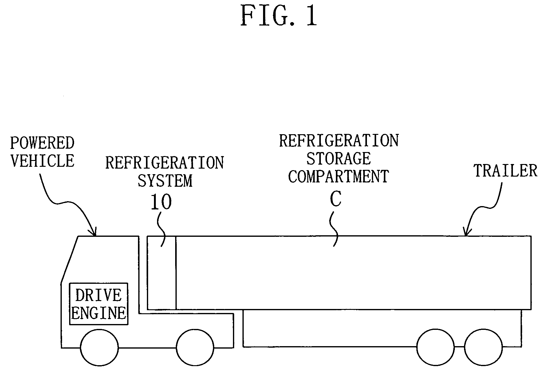
[0068]As shown in FIG. 1, a refrigeration system (10) of the present embodiment is incorporated in a refrigeration vehicle for ground transportation of frozen foods, fresh foods and other foods. This refrigeration vehicle includes a powered vehicle (trailer head) having a driver's cabin and a drive engine, and a cargo-carrying platform vehicle (trailer) having a refrigeration storage compartment (C). The trailer head and the trailer are detachably connected together. The refrigeration system (10) of the present embodiment is mounted on the front side of the cargo-carrying platform vehicle (trailer), and provides cooling of the inside of the refrigeration storage compartment (C).

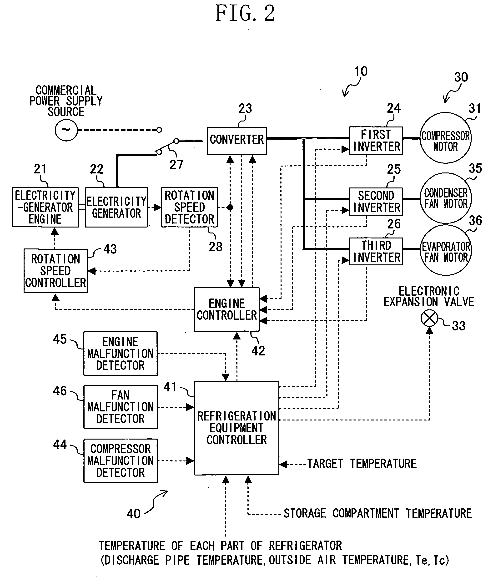
[0069]Referring to FIGS. 2 and 3, the refrigeration system (10) includes an electricity-generator engine (21), an electricity generator (22), a converter (23), three...


PUM


Abstract

A trailer refrigeration system comprising: an electricity generator (22); an electricity-generator engine (21) for driving the electricity generator (22); a converter (23) for converting ac electric power generated by the electricity generator (22) into dc electric power; an inverter (24, 25, 26) including inverters (24), (25), (26) each for converting dc electric power from the converter (23) into ac electric power; a refrigerant circuit (30) having an electric compressor (31) and a fan (35, 36) including fans (35), (36), the electric compressor (31), the fan (35), and the fan (36) being driven respectively by ac electric power from inverters (24), (25), (26); and a control means (40) for individually controlling the speed of rotation of the electric compressor (31), the fan (35), and the fan (36).

Description

TECHNICAL FIELD[0001]In general, the present invention relates to refrigeration systems intended for use in transport trailers. More specifically, the present invention relates to techniques for the reduction in engine size and weight.BACKGROUND ART[0002]In the past, refrigeration systems intended for installation in refrigeration vehicles for ground transportation of frozen foods et cetera and providing cooling of the inside of their refrigeration storage compartments, have been known in the art. In one such refrigeration system, its compressor is driven by electric power generated by the power of a drive engine of the refrigeration vehicle.[0003]However, the problem with this case is that upon the turning off of the drive engine, the compressor, too, is brought to a stop. As a result, the temperature of the inside of the refrigeration storage compartment increases. There is a refrigeration vehicle made up of a powered vehicle (trailer head) having a driver's cabin, and a cargo-car...

Claims


Application Information

Patent Timeline
Patent Type & Authority Applications(United States)
IPC IPC(8): B60H1/32F25D17/06
CPCB60P3/20F25B27/00F25B49/025F25D29/003F25B2600/021F25B2600/111F25B2600/112F25B2327/00
Inventor MATSUNO, SUMIKAZUNAKATA, TETSUOSAWADA, YUZOYAKUSHIJI, FUMIAKINISHIHAMA, YUKIOKUDOU, KEISUKEMIZUTANI, YASUTOSHI
Owner DAIKIN IND LTD
Why Eureka
Try Eureka