
Tuning Bar Vibrator and Vibrating Gyroscope Using the Same

a vibrating gyroscope and tuning bar technology, applied in the direction of acceleration measurement using interia force, turn-sensitive devices, instruments, etc., can solve the problems of limited vibrating gyroscope profile reduction and thickness of piezoelectric substances, so as to reduce the profile, prevent the resonant frequency from being increased, and reduce the profile

Inactive Publication Date: 2009-05-28
MURATA MFG CO LTD
View PDF11 Cites 9 Cited by
  • Summary
  • Abstract
  • Description
  • Claims
  • Application Information

AI Technical Summary

Benefits of technology

[0007]In this way, when the size of the tuning bar vibrator is reduced, the detection sensitivity for a rotational angular velocity decreases, whereas the resonant frequency is reduced in order to increase the detection sensitivity for a rotational angular velocity, the size of the tuning bar vibrator is increased. In addition, in the tuning bar vibrator in which piezoelectric substances are laminated, the thickness of the piezoelectric substances is inevitable and, as a result, a reduction in profile of the vibrating gyroscope is limited.
[0008]For the above reasons, it is a main object of the invention to provide a tuning bar vibrator that is small in size, may be reduced in profile and may be used as a vibrating gyroscope having a desirable detection sensitivity, and a vibrating gyroscope using the tuning bar vibrator.
[0011]In addition, a second detection unit may be formed so as to be connected to each end of the first detection unit and may be formed so as to extend in the longitudinal direction of the vibrating body on each side of the vibrating body in a width direction thereof. By forming the second detection unit at each end of the first detection unit, it is possible to increase deformation of the first detection unit due to Coriolis force, so it is possible to output a further large signal corresponding to Coriolis force from the sensing electrode.
[0012]The vibrating body may be formed by adhering two piezoelectric substrates, and the two piezoelectric substrate adjacent to the one principal surface of the vibrating body and adjacent to the other principal surface of the vibrating body may be polarized in opposite directions with respect to each other in a thickness direction thereof. Moreover, the vibrating body may be formed by adhering a piezoelectric substrate and a non-piezoelectric substrate that are polarized in a thickness direction thereof. Furthermore, the vibrating body may be formed of a thin film that includes a piezoelectric film. The vibrating body just needs to be configured to bend and vibrate by a driving signal. Thus, the vibrating body may be formed by adhering two piezoelectric substrates or the vibrating body may be formed by adhering a piezoelectric substrate and a non-piezoelectric substrate. Furthermore, by forming the vibrating body in a thin-film structure, it is possible to reduce the profile of the tuning bar vibrator.
[0014]According to the invention, even when the tuning bar vibrator is miniaturized, it is possible to prevent the resonant frequency from being increased. Hence, when the tuning bar vibrator is used, it is possible to obtain the miniaturized vibrating gyroscope having a desirable sensitivity. Furthermore, by forming the vibrating body of the tuning bar vibrator in a thin-film structure, it is possible to reduce the profile of the tuning bar vibrator. Hence, when the tuning bar vibrator is used, it is possible to obtain the vibrating gyroscope with a reduce profile.

Problems solved by technology

In addition, in the tuning bar vibrator in which piezoelectric substances are laminated, the thickness of the piezoelectric substances is inevitable and, as a result, a reduction in profile of the vibrating gyroscope is limited.

Method used


Image

  • Tuning Bar Vibrator and Vibrating Gyroscope Using the Same
  • Tuning Bar Vibrator and Vibrating Gyroscope Using the Same
  • Tuning Bar Vibrator and Vibrating Gyroscope Using the Same

Examples


Embodiment Construction

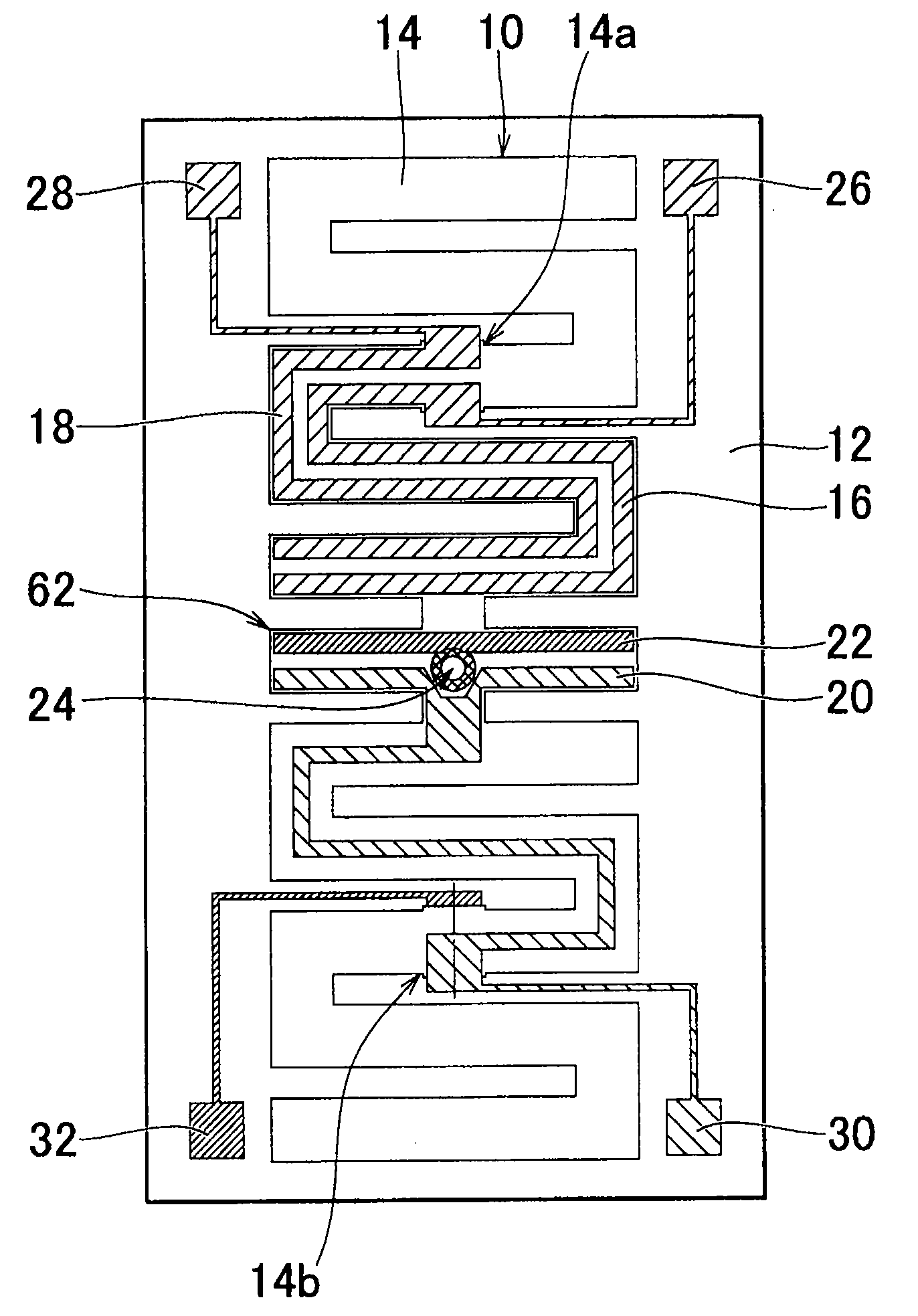
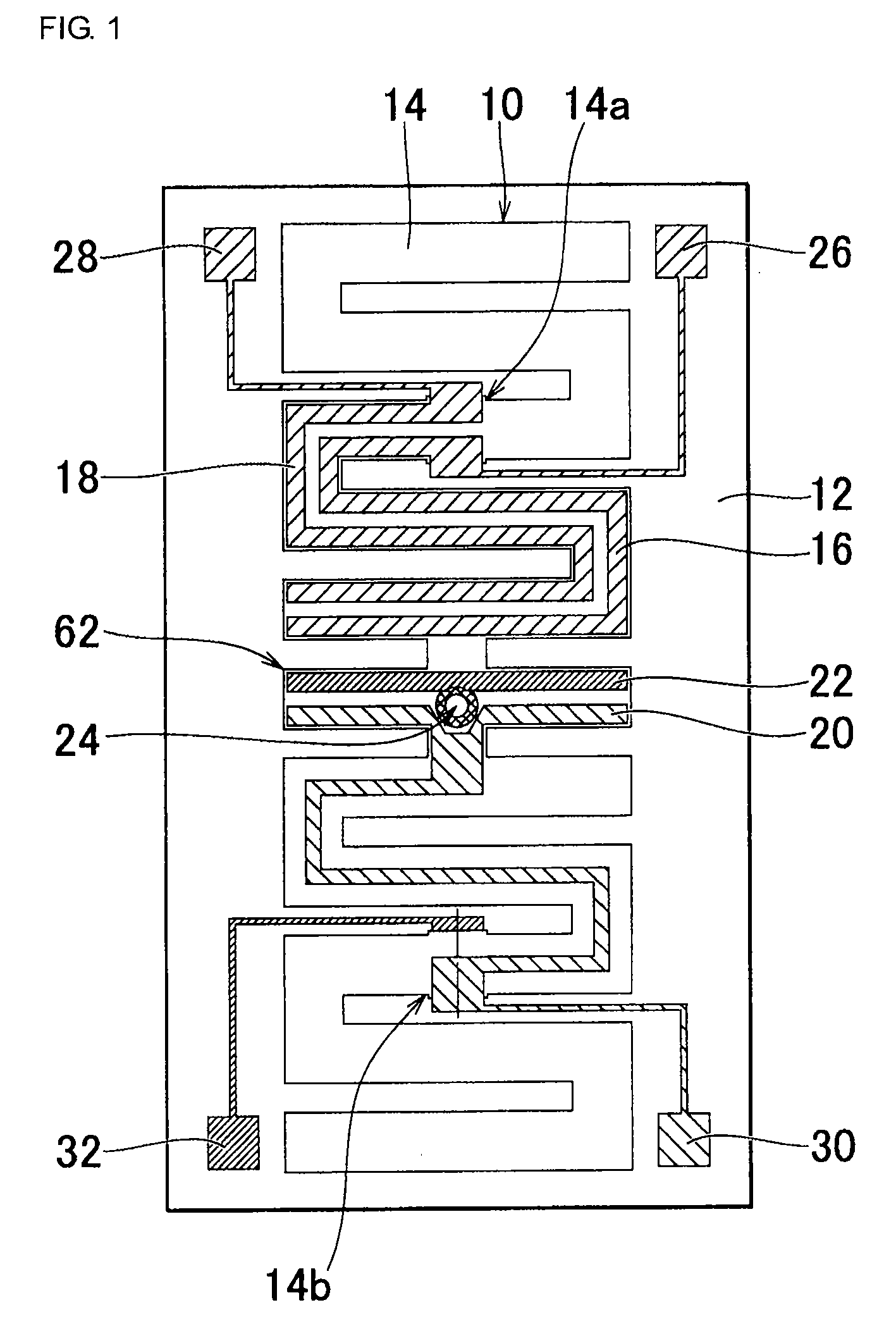
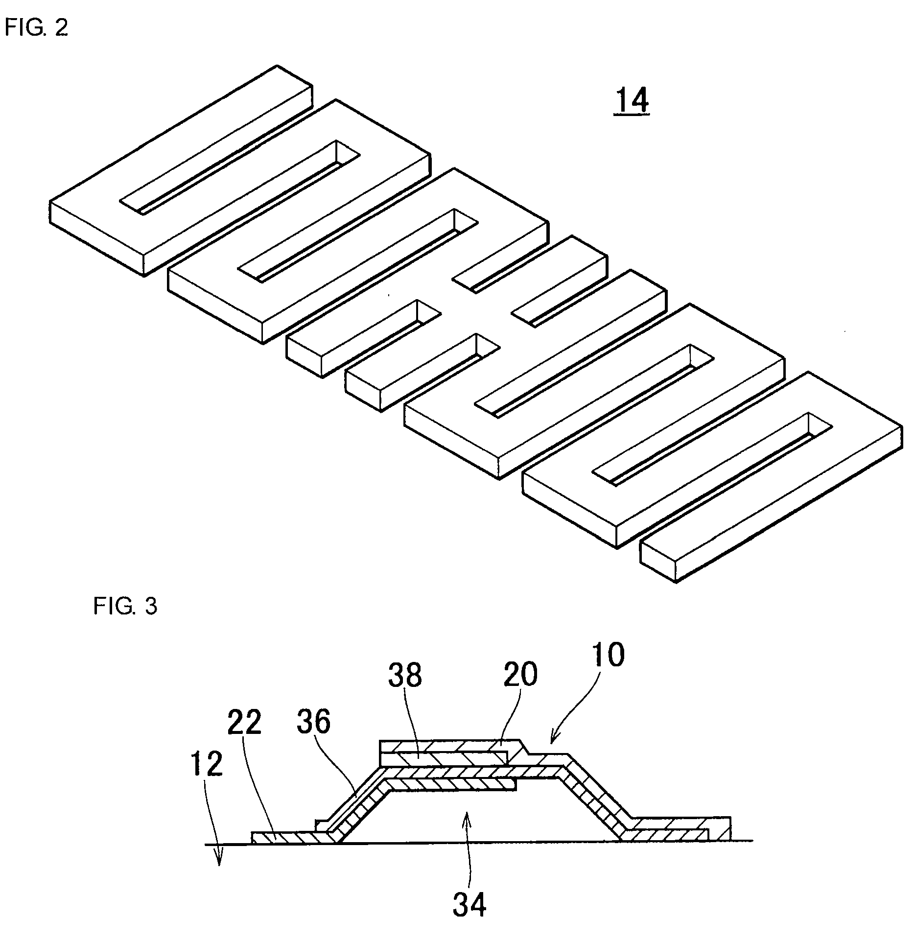
[0045]FIG. 1 is a plan view that shows an example of a tuning bar vibrator of the invention. The tuning bar vibrator 10 is, for example, supported on a rectangular plate-like substrate 12 in a hollow form. The tuning bar vibrator 10 includes a vibrating body 14. The vibrating body 14 is, for example, formed to be a thin film structure with an SiO2 film and a piezoelectric film. The vibrating body 14 is formed in a meander shape overall, as shown in FIG. 2. That is, a plurality of rectangular vibrating reeds are arranged parallel to one another, and the middle vibrating reed is connected to the adjacent vibrating reeds at the centers. In addition, at both sides of the connected three vibrating reeds, the respective vibrating reeds are connected alternately at different ends to form a serpentine meander shape. On both sides of the middle vibrating reed, adjacent vibrating reeds are connected at opposite ends with respect to each other so as to be formed symmetrically with respect to t...


PUM


Abstract

A tuning bar vibrator formed on a substrate and including a vibrating body. The vibrating body is formed into a meander shape as a whole, and a middle vibrating reed is used as a first detection unit. At one end side of the vibrating body, two sensing electrodes are formed and connected respectively to two extended electrodes. A further sensing electrode and a common electrode are formed on a first principal surface of the first detection unit. A common electrode formed on a second principal surface of the vibrating body is connected to the common electrode on the first principal surface via a through-hole. The further sensing electrode and the common electrode are connected respectively to another set of extended electrodes. A tuning bar vibrator that is small in size, may be reduced in profile and may be used as a vibrating gyroscope having a desirable detection sensitivity, and a vibrating gyroscope using the tuning bar vibrator are obtained.

Description

CROSS REFERENCE TO RELATED APPLICATIONS[0001]The present application is a continuation of International Application No. PCT / JP2007 / 057825, filed Apr. 9, 2007, which claims priority to Japanese Patent Application No. JP2006-199147, filed Jul. 21, 2006, the entire contents of each of these applications being incorporated herein by reference in their entirety.FIELD OF THE INVENTION[0002]The invention relates to a tuning bar vibrator and a vibrating gyroscope using the same and, more particularly, to, for example, a tuning bar vibrator that utilizes bending vibration and a vibrating gyroscope using the same.BACKGROUND OF THE INVENTION[0003]FIG. 12 is a perspective view that shows an example of an existing tuning bar vibrator. The tuning bar vibrator 1 includes two rectangular piezoelectric substrates 2a and 2b. These piezoelectric substrates 2a and 2b are laminated via an electrode 3. These piezoelectric substrates 2a and 2b are polarized in opposite directions to each other as shown by...

Claims


Application Information

Patent Timeline
Patent Type & Authority Applications(United States)
IPC IPC(8): G01C19/56G01C19/5621G01C19/5628
CPCG01C19/5621H03H9/21G01C19/5656
Inventor FUJIMOTO, KATSUMIKOIKE, MASATO
Owner MURATA MFG CO LTD
Learn More