Method and plant for manufacturing cement clinker

a technology of cement clinker and manufacturing method, which is applied in the direction of furnaces, furnace types, lighting and heating apparatus, etc., can solve the problems of gate getting stuck, difficult to provide a gate which is capable of operating reliably at such a temperature, etc., and achieve the effect of reducing the risk of clogging

Active Publication Date: 2009-05-28
F L SMIDTH & CO AS
View PDF2 Cites 5 Cited by
  • Summary
  • Abstract
  • Description
  • Claims
  • Application Information

AI Technical Summary

Benefits of technology

[0007]It is hereby obtained that the quantity of material which is extracted by means of the additional cyclone can be adjusted by means of known means in a more reliable manner than has hitherto been possible, while also significantly reducing the risk of alkali-induced clogging. This is due to the fact that the lower temperature allows utilization of generally known control means and the fact that the alkali in the gases will condense and settle on particles in the gases at temperatures which are lower than 850° C.
[0009]A further disadvantage of the plant shown in WO 2005 / 100247 is that its productive capacity is reduced in comparison with a plant without an additional separation cyclone because the gases from the additional separation cyclone are returned to the preheater. This disadvantage can to some extent be reduced by increasing the capacity of the fan which draws the gases through the kiln system. However, this is not an optimum solution, and it is therefore preferred that the gases from the additional separation cyclone are diverted via a separate system comprising a separate fan. Hence it will be possible to maintain the productive capacity of the plant independent of the quantity of calcined raw material being extracted via the additional cyclone.
[0012]In principle, this additional, separate calciner can be fed with exit gases from the kiln, but it is, however, preferred that it is fed with air from the clinker cooler. This will reduce the amount of alkali in the separate system to a negligible level, significantly reducing the risk of clogging.

Problems solved by technology

Typically, the temperature of the gases which are diverted via the discharge duct from the additional cyclone will be about 900° C., and in actual practice it has proved to be very difficult to provide a gate which is capable of operating reliably at such a temperature.
Also, the gases may contain some amount of alkali which may be quite sticky due to the high temperature, and therefore having a tendency to clog at and around the gate, entailing risk of the gate getting stuck.

Method used


Image

  • Method and plant for manufacturing cement clinker
  • Method and plant for manufacturing cement clinker
  • Method and plant for manufacturing cement clinker

Examples


Embodiment Construction

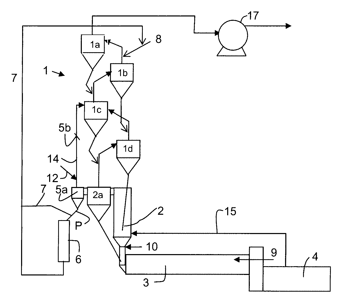
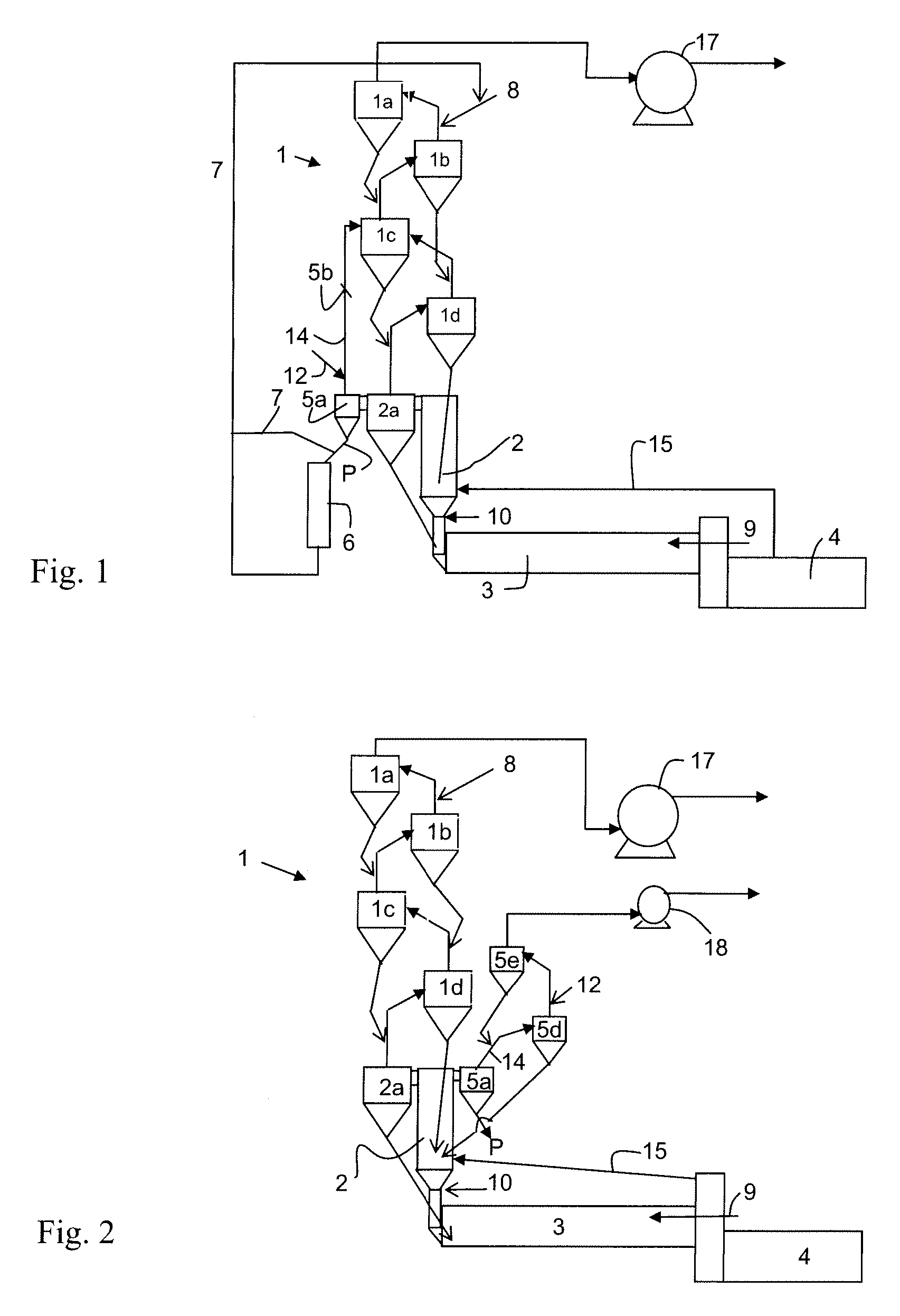
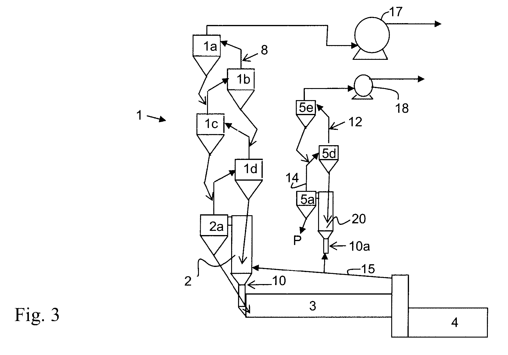
[0019]In FIG. 1 is seen a cement manufacturing plant which comprises a cyclone preheater 1 with four cyclone stages 1a to 1d, a calciner 2 with a separation cyclone 2a, a rotary kiln 3 and a clinker cooler 4. The plant operates in traditional manner with the raw materials being introduced at an inlet 8 in the inlet duct for the first cyclone stage 1a of the cyclone preheater and they are heated, calcined and burned into clinker by being transported first through the preheater 1, the calciner 2, and then the rotary kiln 3 in counterflow to hot exit gases which are generated at a burner 9 in the rotary kiln 3 and a burner 10 in the calciner 10, respectively, and being drawn through the plant by means of a fan 17. The burned clinker is subsequently cooled in the clinker cooler 4 from which cooling air via a duct 15 is directed to the calciner 2. The plant further comprises an additional separation cyclone 5a which is mounted parallel to the separation cyclone 2a. The separation cyclone...


PUM

PropertyMeasurementUnit
temperatureaaaaaaaaaa
temperaturesaaaaaaaaaa

Abstract

Manufacturing methods and plants for carrying out methods of manufacturing cement clinker including diverting gases from a separation cyclone for a calcined cement material. The diverted gases are cooled to a temperature of 850° C. or less by introducing raw cement materials into the diverted gas stream.

Description

CROSS REFERENCE TO RELATED APPLICATIONS[0001]This application is a filing under 35 U.S.C. § 371 of PCT / EP2007 / 052688 filed Mar. 21, 2007, which claims the benefit of Denmark Application No. PA 2006 00657 filed May 10, 2006, each of which is hereby incorporated by reference in its entirety.BACKGROUND OF THE INVENTION[0002]The present invention relates to manufacturing plants and methods for manufacturing cement clinker.[0003]A method and a plant of the aforementioned kind are known e.g. from WO 2005 / 100247. In this known plant a portion of the calcined raw meal is extracted using a small additional cyclone which is positioned parallel to the separation cyclone of the calciner. According to the patent application the quantity of material which is extracted by means of the additional cyclone can be adjusted using a gate which is located in the discharge duct for the gases from the aforementioned additional cyclone. Typically, the temperature of the gases which are diverted via the disc...

Claims


Application Information

Patent Timeline
Patent Type & Authority Applications(United States)
IPC IPC(8): C04B2/10F27B15/00
CPCC04B7/365F27B7/2041F27B7/2033
Inventor HANSEN, JENS PETER
Owner F L SMIDTH & CO AS
Why Eureka
Try Eureka