
Shock absorber

a shock absorber and shock technology, applied in the field of single-shock absorbers, can solve problems such as system damage and man damag

Inactive Publication Date: 2009-05-28
RAPID RAIL INT
View PDF9 Cites 36 Cited by
  • Summary
  • Abstract
  • Description
  • Claims
  • Application Information

AI Technical Summary

Benefits of technology

[0012]In this way, when a load of a predetermined value is applied to the two load application points, there is controlled spatial separation of the two load points with a resultant absorption of energy by the shock absorber thereby reducing the rate of fall of a falling load, such as an initially free falling man at a level which does not expose him to damaging shock loads, and does not over-load the fall arrest system in which the shock absorber is incorporated.
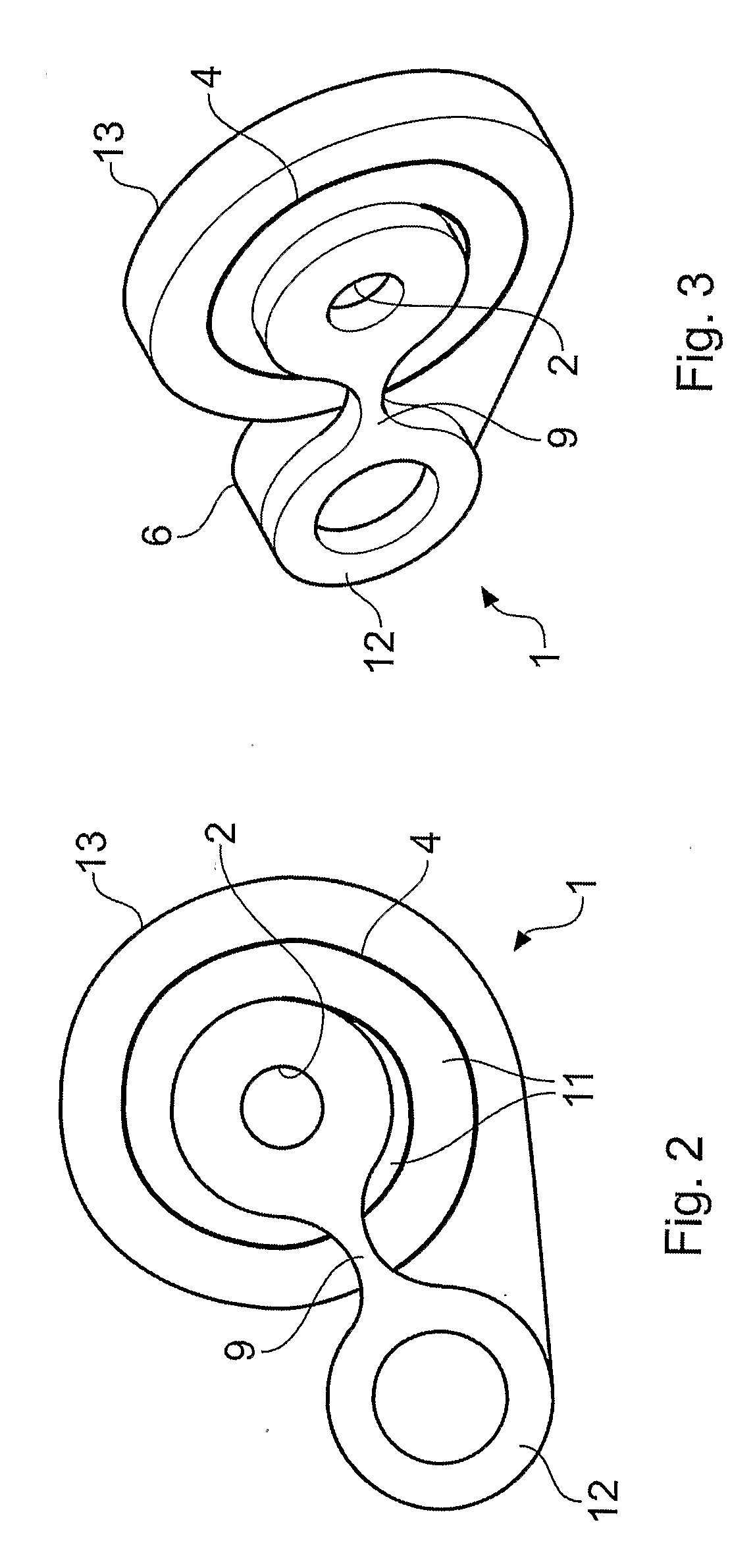
[0025]When the deformable element unwinds under tension, it stops unwinding when the final load point is reached i.e. the deformable element stops unwinding when the deformable element spiral formation has fully unwound, and is capable of continuing to support a load even when fully unwound. In other words, once the deformable element has unwound under tension, the shock absorber is able to support a load and does not tear under continuing applied tension. Thus, any falling load, such as a falling person whose fall is arrested and whose shock load is absorbed at least in part through the unwinding of the deformable element will not resume falling when the deformable element has unwound. Instead, the unwound deformable element will be capable of supporting the load or person whose fall has been arrested, such that the load or person is prevented from falling further.

Problems solved by technology

These can be damaging to the system and the man.
A problem with a device that is intended to deform plastically under shock loading may deform appreciably elastically under lesser loads to such extent as to interfere with other devices under ordinary usage.

Method used


Image

  • Shock absorber
  • Shock absorber
  • Shock absorber

Examples


Embodiment Construction

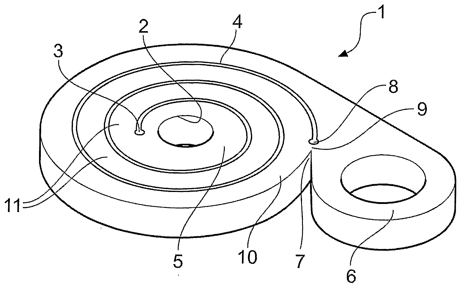
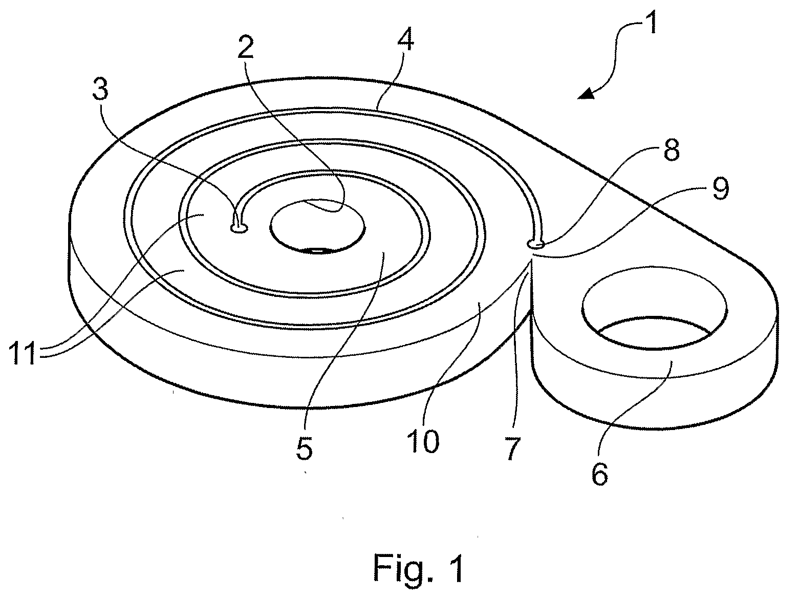
[0044]Referring to the drawing, the shock absorber 1 is laser cut from stainless steel. It has a 10 mm central bore 2 via which it attaches to an element of a fall arrest system or the like using a pin, axle or the like (neither shown) to apply load. From a crack limitation drilling 3, a spiral laser cut 4 spirals out 2.5 or other desired number of turns, leaving a spiral element ranging from 5 mm to 14 mm between the cuts depending on energy absorption requirement. A complete inner eye 5 is left around the central bore 2. The shock absorber 1 has a thickness of 8 mm.

[0045]The laser cut terminates at an outer eye 6 with a 18 mm bore for attachment of a karabiner via a webbing link (neither shown). In use, the karabiner couples load from a man using the shock absorber in a fall arrest system to a standing part of the system, via further parts of the system which are not shown.

[0046]The outer contour of the shock absorber is laser cut, with a re-entrant 7, which approaches within 2 mm...


PUM


Abstract

A single-shock-use shock absorber having a first load application point; a second load application point; a deformable element between the points, the element being dimensioned for plastic shock absorbing deformation: and a bridge between the first and second load application points, the bridge dimensioned to fracture at a predetermined load less than that at which the element deforms plastically. Also provided is a single-shock-use shock absorber comprising a first load application point; a second load application point; a deformable element between the points, the element being dimensioned for plastic shock absorbing deformation, the deformable element having a first and a second slot extending into the deformable element from opposing sides. Also provided is a fall arrest device incorporating one or more of the aforementioned shock absorbers and a fall arrest system incorporating one or more of the aforementioned fall arrest devices.

Description

BACKGROUND TO THE INVENTION[0001]The present invention relates to a single-shock-use shock absorber.[0002]It is known for fall arrest systems to incorporate a shock absorber in which a textile element tears at stitching and / or stitched fabric to absorb energy in decelerating a falling man prior to the force arising from his full momentum being resisted by a rope or cable alone. If a shock absorber is not provided, much higher shock loads are experience throughout the fall arrest system and indeed by the man. These can be damaging to the system and the man.[0003]It is known to absorb shock by plastic deformation, typically of a single-shock-use metallic element.[0004]By single-shock-use is intended that the element may carry loads well below the load at which it deforms plastically, but once it has deformed plastically, it should be discarded.[0005]A problem with a device that is intended to deform plastically under shock loading may deform appreciably elastically under lesser loads ...

Claims


Application Information

Patent Timeline
IPC IPC(8): A62B35/04F16F7/00F16F7/12F16F7/14
CPCA62B35/04F16F7/14F16F7/123F16F7/003E04G21/3204F16F7/12F16F7/128
Inventor WARREN, BERNARD R.
Owner RAPID RAIL INT
Learn More