Purified Water Production and Distribution System

a technology of purified water and distribution system, applied in the direction of membranes, filtration separation, separation processes, etc., can solve the problems of increasing energy consumption, affecting the quality of purified water, and introducing additional disinfection problems, so as to maintain the microbiological cleanliness of the system and reduce water wastag

Inactive Publication Date: 2009-05-28
OSMOFLO
View PDF17 Cites 66 Cited by
  • Summary
  • Abstract
  • Description
  • Claims
  • Application Information

AI Technical Summary

Benefits of technology

[0041]Hence it will be seen that the invention provides a system which produces and distributes purified water of microbiological quality to points of usage on demand using single or double pass reverse osmosis configurations without the use of a storage tank. The invention uses a combination of water recirculation a

Problems solved by technology

This is because the water purity specifications allow for an amount of biological contaminant that can, over time, find sites within the device system to inhabit and proliferate or there could be an adverse event causing contamination of the device.
However, the problem with this system is there is no heat disinfection upstream of the reverse osmosis membranes unless some heated product water is routed upstream of the reverse osmosis membranes by the use of valving and additional piping for this purpose during the disinfection process.
This may introduce additional disinfection problems.
Another drawback of this system is that the storage tank will not be exposed to the fluid velocities required to inhibit bio-film formation, may have sta

Method used


Image

  • Purified Water Production and Distribution System
  • Purified Water Production and Distribution System
  • Purified Water Production and Distribution System

Examples


Embodiment Construction

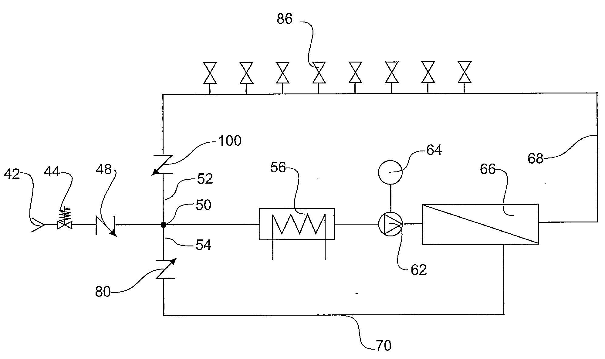
[0053]The reverse osmosis filtration unit shown in FIG. 4 is a closed loop filtration and supply unit according to one embodiment of the invention.

[0054]Feed water that has been pre-treated to meet the feed water requirements for reverse osmosis purification is provided to the invention at inlet 42. The feed water passes through a pressure regulator, 44 and a non return valve or backflow prevention device 48 to junction 50. The junction 50 connects the feed water with a purified product water recycle input 52 and reject water recycle input 54, mixing with the feed water. The mixed water passes a heating device 56 before passing to high pressure feed pump 62 driven by a variable frequency controlled motor 64 that provides the required flow rate.

[0055]The mixed water is pumped by pump 62 into an reverse osmosis membrane bank 66. The reverse osmosis membranes will be of the type suitable for heat disinfection. Reverse osmosis reject water line 70 passes to a backflow prevention device ...


PUM

PropertyMeasurementUnit
Pressureaaaaaaaaaa
Electrical conductivityaaaaaaaaaa
Permeation propertiesaaaaaaaaaa

Abstract

A closed loop water purification system comprising a feed water line (42) to supply feed water, a high pressure feed pump (62), a filter assembly (66) having an inlet supplied by the high pressure feed pump, a distribution line (68) and a reject water line (70), the reject line returning reject water from the filter assembly to the feed water line, the distribution line supplying at least one purified water take off point (86) and returning to a junction (50) in the feed water line upstream of the high pressure feed pump. The reject water line is connected to the junction in the feed water line upstream of the high pressure feed pump. A first backflow prevention device (48) is on the feed water line upstream of the junction. A second backflow prevention device (100) is on the distribution line upstream of the junction and a third backflow prevention device (80) is on the reject water line upstream of the junction. A heater system (56) is in one of the distribution line, the reject line or the feed water line.

Description

INTRODUCTION[0001]This invention relates to a water purification and distribution system that can maintain the microbiological purity of the purified water.BACKGROUND[0002]There are presently a variety of industrial and medical devices used to purify water to meet microbiological purity requirements. Water microbiological purity is generally measured by culturing and counting the number of biological cells and / or the by-products of damaged or dead biological cells in a given water sample volume. The water microbiological purity requirements for an application are most often stated in terms of maximum limits for Colony Forming Units (CFU) and Endotoxin Units (EU) per millilitre of water, that is, CFU / ml and EU / ml respectively. Typically, requirements for specific applications are tabled in standards such as ANSI / AAMI RD62.[0003]Conventional devices for water purification include, but are not limited to, the application of Chlorination / Dechlorination systems, Mechanical Filtration, Ul...

Claims


Application Information

Patent Timeline
IPC IPC(8): C02F1/44C02F1/02
CPCB01D61/022B01D61/025C02F2303/04C02F2209/40C02F2209/05B01D61/04B01D61/12B01D65/02B01D2311/04B01D2311/103B01D2311/165B01D2315/12B01D2321/08C02F1/44C02F1/441C02F2209/00C02F2209/005C02F2209/02B01D2311/243B01D61/026
Inventor FABIG, MARCUS JOHN
Owner OSMOFLO
Why Eureka
Try Eureka