
Method and apparatus for monitoring gateroad structural change

a technology of structural change and gate road, applied in seismology for waterlogging, instruments, reradiation, etc., can solve the problems of large stress in the region surrounding the gateway, deformation of the overall gate road structure, and difficulty in detection

Active Publication Date: 2009-05-28
COMMONWEALTH SCI & IND RES ORG
View PDF4 Cites 33 Cited by
  • Summary
  • Abstract
  • Description
  • Claims
  • Application Information

AI Technical Summary

Benefits of technology

[0016]a scan difference processor to permit noting of differences in information of first scan and the second scan, whereby a gateroad structural change can be determined

Problems solved by technology

The process of removing the product from the product panel can, however, introduce large stresses in regions surrounding the gateways.
The stresses, however, produce other local features in the gateroads which can lead to deformation of the overall gateroad structure over time.
Convergence represents a subtle and dangerous form of stress-induced gateroad deformation because it usually occurs at a rate which is imperceptible to the unaided human eye and this makes it difficult to detect.
Failure to note gateroad convergence can lead to collapse and failure of the gateroads themselves and can result in severe safety hazards to personnel and equipment.
The method is dependent on manual operation of the extensometer device and is invasive, and often is required to be performed in a hazard area.
It is not until after the manual measurement is made with the extensometer device that the human operator can ascertain that there has been excessive convergence resulting in a hazardous situation.
Further, such methods can be obstructive to the normal passage of the gateroad traversing structure of a mining machine installation used for mining product from the product face.

Method used


Image

  • Method and apparatus for monitoring gateroad structural change
  • Method and apparatus for monitoring gateroad structural change
  • Method and apparatus for monitoring gateroad structural change

Examples


Embodiment Construction

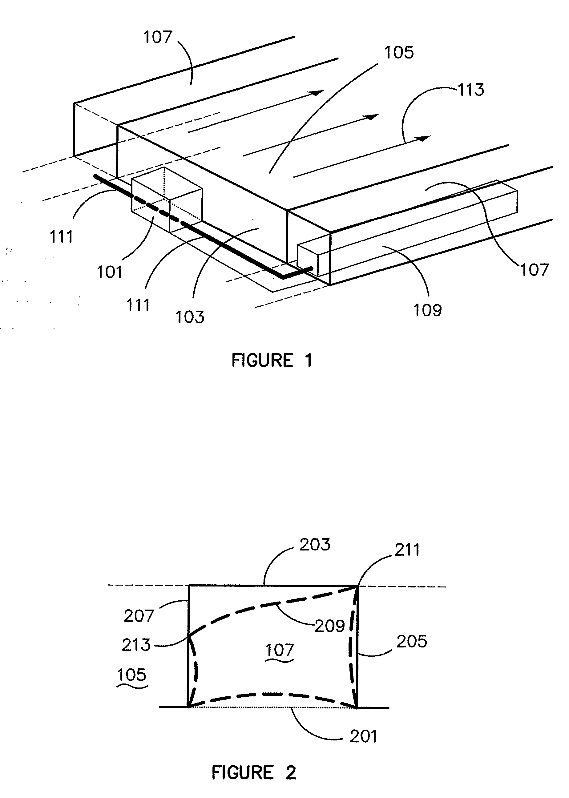
[0026]FIG. 1 is a diagrammatic view showing a 3D cut-away of a longwall underground coal mining operation (not to scale). Here, there is a provided a longwall shearer 101 that traverses from side to side across a coal panel 103 in a coal seam 105. At each side of the coal seam 105 there are provided rectangular shaped roadways known as gateroads 107. The gateroads 107 are cut into the strata and / or the coal seam 105 so that the direction and size of the gateroads 107 conforms to accurate parameters such as size and 3D positioning and direction. Typically, the gateroads 107 run parallel to one another. A gateroad traversing structure 109 is provided in one or both of the gateroads 107. Mechanical linkage 111 connects the gateroad traversing structure 109 and the shearer 101. Typically, the mechanical linkage 111 is a rail track means on which the shearer 101 can traverse.

[0027]The gateroad traversing structures 109 form part of the mining machine installation associated with mining, ...


PUM


Abstract

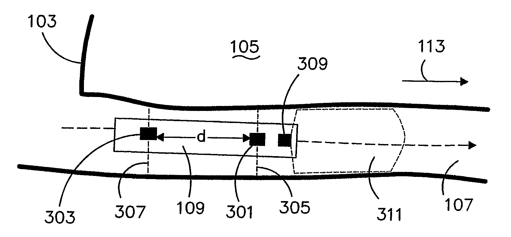
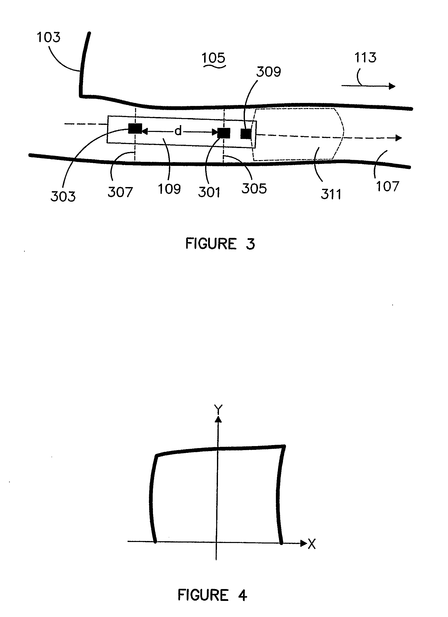
A method and apparatus is provided for determining structural change in a mining operation. A first scan of gateroad surfaces is obtained and information of the scan profile is stored. At a later time a second scan of the gateroad surfaces is then obtained. Information of the scans can be registered and any difference noted. If the difference exceeds a threshold a warning can be provided indicating a gateroad structural change that may be hazardous. The scans can be made from a single sensor, or from multiple sensors (301, 303). In the case where the sensors (301, 303) are mounted on a gateroad traversing structure (109), the distance of spacing of the sensors (301, 303) can be used to determine when the sensor (303) has reached a position of movement or travel of the gateroad traversing structure (109) where the scan from sensor (301) was made. A distance sensor (309) can be provided to determine the distance of movement and where the scans coincide.

Description

FIELD OF THE INVENTION[0001]This invention relates to a method and apparatus for monitoring gateroad structural change in a mining operation and relates particularly but not exclusively to use in longwall mining processes such as those used for coal extraction.BACKGROUND[0002]Longwall mining is one of the most efficient methods for underground coal recovery where a large panel of coal, bounded by roadways (gateroads) is extracted by means of a mechanised shearing apparatus. The gateroads provide access for equipment and personnel and are essential to the longwall mining process.[0003]The normal process of longwall mining involves removing product from the face of a product panel while progressively retreating in the direction of a gateroad. Thus, as the mining progresses, a mining machine installation moves down a gateroad and carries with it a shearing apparatus that shears product from the product panel. The movement into the product panel in the direction of the gateroad is terme...

Claims


Application Information

Patent Timeline
Patent Type & Authority Applications(United States)
IPC IPC(8): E21F17/00
CPCE21F17/185
Inventor HARGRAVE, CHAD OWENRALSTON, JONATHON CAREYKELLY, MICHAEL SHAWN
Owner COMMONWEALTH SCI & IND RES ORG
Learn More