Wipe pattern generation apparatus

a pattern generation and pattern technology, applied in the direction of memory adressing/allocation/relocation, instruments, color signal processing circuits, etc., can solve the problem of giving unnatural sense to the viewer, and achieve the effect of high speed

Inactive Publication Date: 2009-05-28
GK BRIDGE 1
View PDF13 Cites 14 Cited by
  • Summary
  • Abstract
  • Description
  • Claims
  • Application Information

AI Technical Summary

Benefits of technology

[0024]According to the invention, there can be provided a wipe pattern generation apparatus that can generate wipe patterns of various shapes at high speed and moreover can be miniaturized.

Problems solved by technology

However, to switch a scene in the same program or to switch the program, the continuity of the frame images output in sequence is interrupted suddenly and thus there is a possibility that an unnatural sense may be given to the viewer.

Method used


Image

  • Wipe pattern generation apparatus
  • Wipe pattern generation apparatus
  • Wipe pattern generation apparatus

Examples


first embodiment

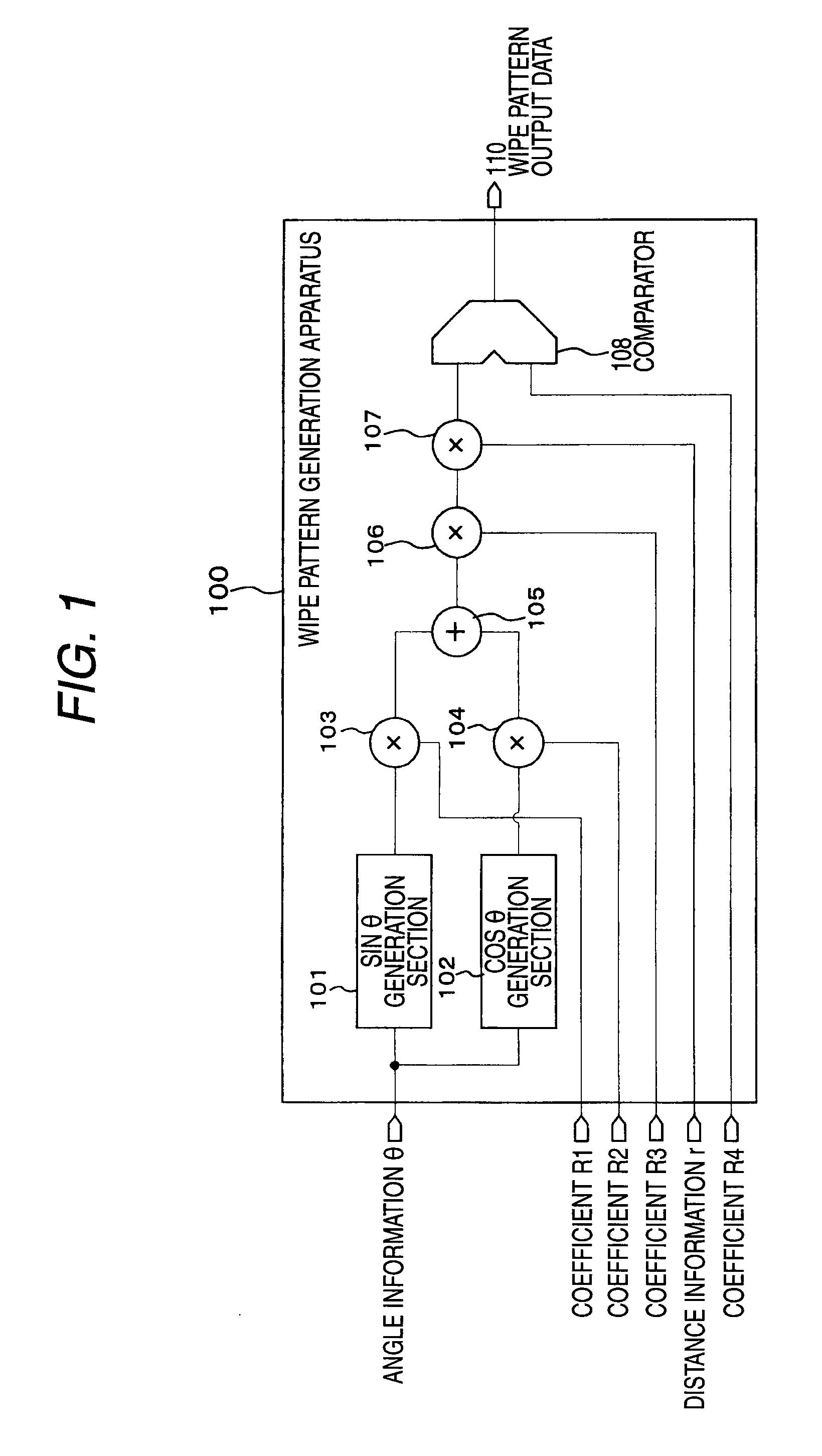
[0106]FIG. 1 is a block diagram to show the configuration of a wipe pattern generation apparatus according to a first embodiment of the invention. A wipe pattern generation apparatus 100 of the embodiment is made up of a sin θ generation section 101, a cos θ generation section 102, a multiplier 103, a multiplier 104, an adder 105, a multiplier 106, a multiplier 107, and a comparator 108.

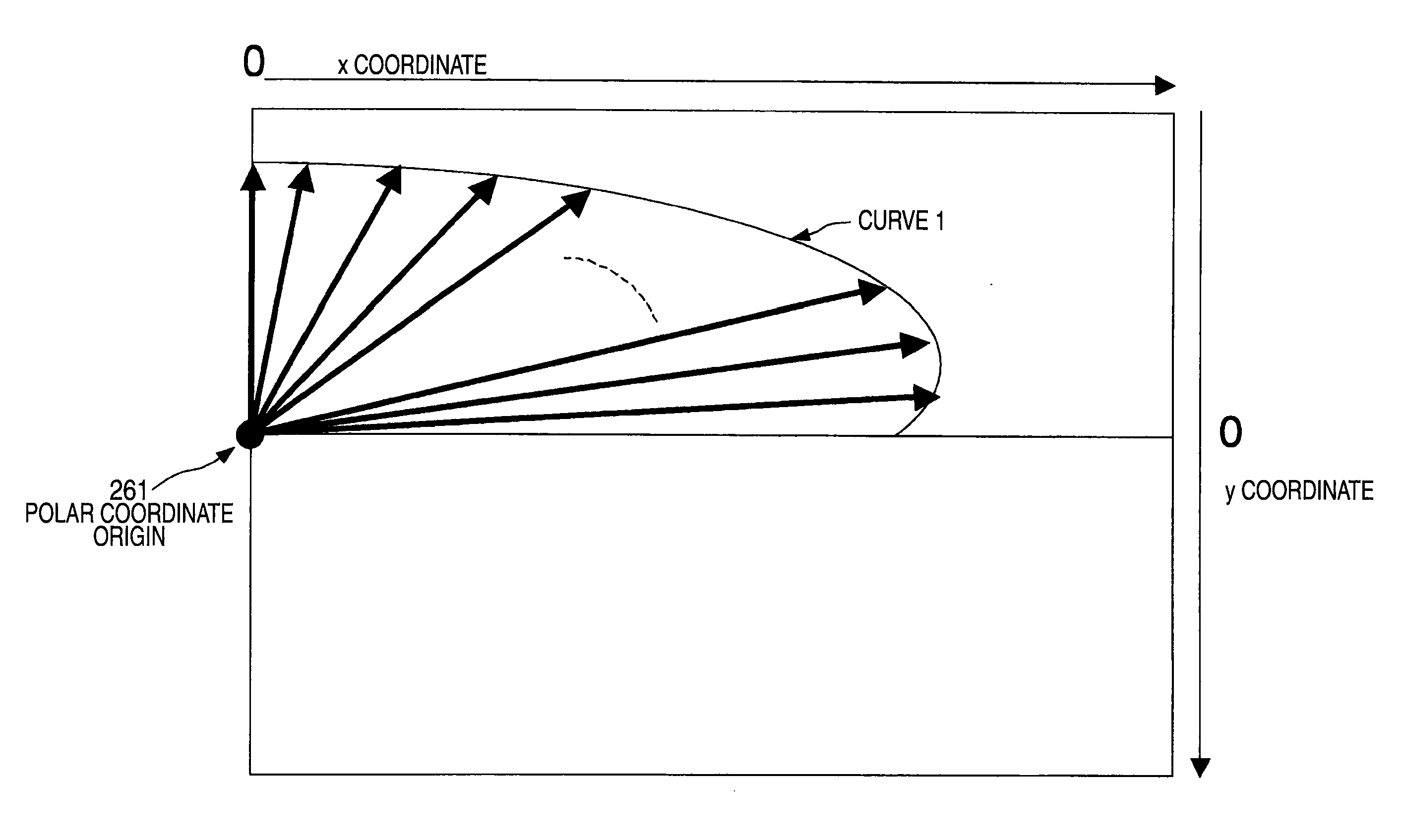
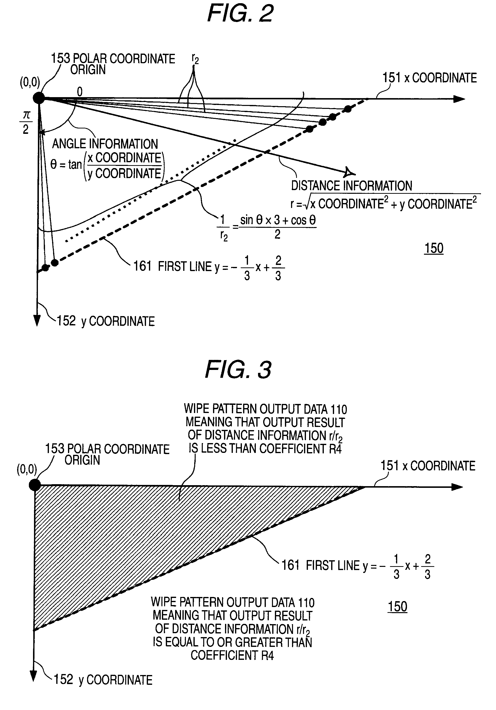
[0107]Information representing each pixel position obtained by scanning over a display screen in sequence in an x coordinate 151 direction and a y coordinate 152 direction by polar coordinates, namely, angle information θ and distance information r are input to the wipe pattern generation apparatus 100. In addition, the numeric values of coefficients R1, R2, R3, and R4 for determining the characteristic of the wiper pattern to be generated are also input to the wipe pattern generation apparatus 100.

[0108]The sin θ generation section 101 calculates data of sin θ from the input angle information θ of p...

second embodiment

[0128]FIG. 6 is a block diagram to show a first configuration example of the main part of a wipe pattern generation apparatus according to a second embodiment of the invention, and FIG. 7 is a block diagram to show a second configuration example of the main part of the wipe pattern generation apparatus according to the second embodiment of the invention.

[0129]The wipe pattern generation apparatus includes a θ range detection section 231, a circuit configuration switching section 232, a dynamic reconfiguration (Reconfigurable Compute Fabric) device RCF, a multiplier 211, and a comparator 259. In the wipe pattern generation apparatus of the second embodiment, the function of a first circuit 212 is implemented in the dynamic reconfiguration device RCF as shown in FIG. 6 under one condition and the function of a second circuit 224 is implemented in the dynamic reconfiguration device RCF as shown in FIG. 7 under another condition as described later.

[0130]For example, MRC6011 manufactured...

third embodiment

[0170]FIG. 20 is a block diagram to show a configuration example of the main part of a wipe pattern generation apparatus according to a third embodiment of the invention. FIG. 21 is a schematic drawing to show a specific example of a wipe pattern in the wipe pattern generation apparatus of the third embodiment.

[0171]The third embodiment is a modified example of the second embodiment described above. Components similar to those of the second embodiment are denoted by the same reference numerals in FIGS. 20 and 22. The description to follow centers on the configuration and the operation different from those of the second embodiment.

[0172]The third embodiment assumes the case where a wipe pattern as shown in FIG. 21 is applied to a display screen. In FIG. 21, a pixel position in a horizontal direction in the display screen is an x coordinate and a pixel position in a vertical direction is a y coordinate and the origin of the x coordinate is the upper left corner of the screen and the o...


PUM


Abstract

A wipe pattern generation apparatus that can generate wipe patterns of various shapes at high speed and moreover can be miniaturized. is provided.
A wipe pattern generation apparatus 100 includes a sin θ generation section 101 for calculating sin θ from input angle information θ; a multiplier 103 for multiplying the calculation result of sin θ by a first coefficient; a cos θ generation section 102 for calculating cos θ from the angle information θ; a multiplier 104 for multiplying the calculation result of cos θ by a second coefficient; a multiplier 106 for multiplying the result of adding output of the multiplier 103 and output of the multiplier 104 by a third coefficient and outputting as the reciprocal of the distance from the polar coordinate center to an arbitrary line on a display screen; a multiplier 107 for multiplying output of the multiplier 106 by distance information r; and a comparator 108 for making a comparison between output of the multiplier 107 and a fourth coefficient, and generates wipe pattern output data 110 from the angle information θ and the distance information r.

Description

TECHNICAL FIELD[0001]This invention relates to a wipe pattern generation apparatus used for video production, etc., and in particular to a wipe pattern generation apparatus that can generate a large number of types of wipe patterns.BACKGROUND ART[0002]For example, in video produced as a moving image like TV broadcasting, usually a large number of frame images consecutive in time series are switched in sequence at given time intervals (for example, 1 / 60-second frame period) for output. However, to switch a scene in the same program or to switch the program, the continuity of the frame images output in sequence is interrupted suddenly and thus there is a possibility that an unnatural sense may be given to the viewer. In such a case, gradual switching is performed from a frame image of the preceding scene to a frame image of the following scene, whereby the viewer can be reliably informed of scene transition.[0003]At the switching time, two areas are formed in the same screen and the f...

Claims


Application Information

Patent Timeline
Patent Type & Authority Applications(United States)
IPC IPC(8): G06T11/20
CPCH04N5/265H04N5/262
Inventor TSUBOTA, KAZUHIROIZUMI, HIROYUKI
Owner GK BRIDGE 1
Why Eureka
Try Eureka