
Image processing method of removing flaw and device using the same

a technology of image processing and flaw removal, applied in the field of image processing method and device using the same, can solve the problems of increasing scanner cost, increasing scanner cost, and increasing scanner cost b>10/b>, so as to reduce manufacturing costs and remove flaws.

Inactive Publication Date: 2009-05-28
QUISDA CORP
View PDF3 Cites 10 Cited by
  • Summary
  • Abstract
  • Description
  • Claims
  • Application Information

AI Technical Summary

Benefits of technology

[0010]The invention is directed to an image processing method of removing flaw and a device using the same. The image processing method removes the flaw without using any additional elements, hence reducing manufacturing costs.

Problems solved by technology

If information is stored in a non-digital format, then scratch, dust or shear marks may easily occur especially on the films.
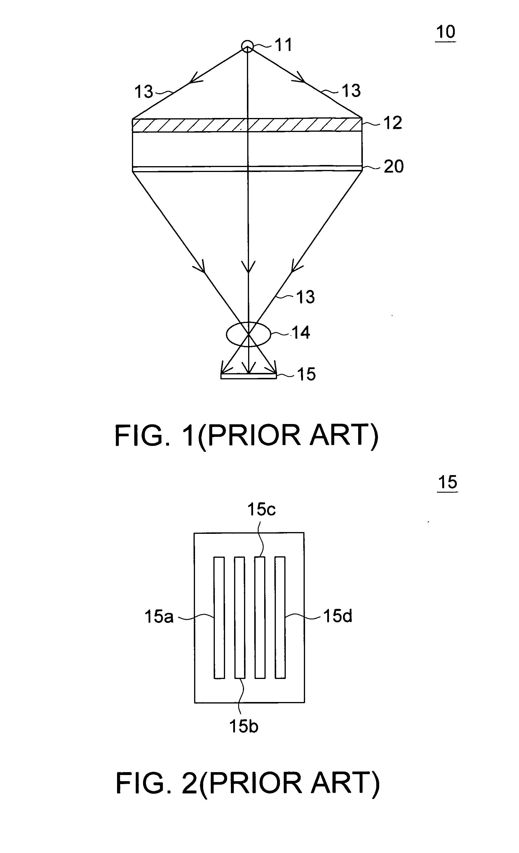
However, the above two methods result in an increase in scanner cost.
Thus, no matter which conventional method is used, the cost of the scanner 10 will increase.
Therefore, how to provide an economic scanner capable of removing scratches and shear marks from film image has become an imminent issue to be resolved.

Method used


Image

  • Image processing method of removing flaw and device using the same
  • Image processing method of removing flaw and device using the same
  • Image processing method of removing flaw and device using the same

Examples


first embodiment

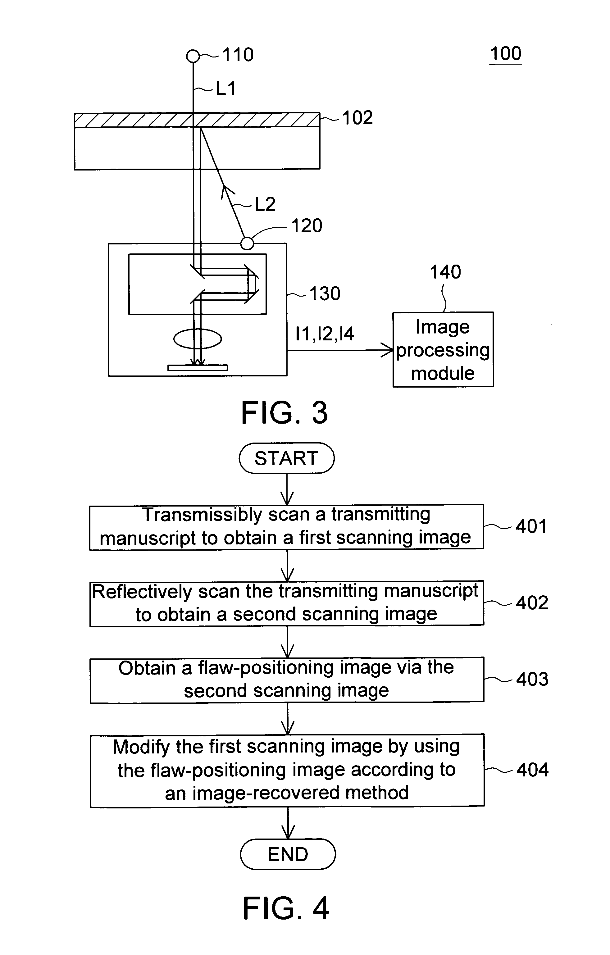
[0026]Referring to FIG. 3, a perspective of an image processing device according to a first embodiment of the invention is shown. The image processing device 100 is used in a transparent manuscript 102. The image processing device 100 includes a transparent scanning light source 110, a reflective scanning light source 120, a scanning module 130 and an image processing module 140. The transparent scanning light source 110 is for generating a first light L1. The reflective scanning light source 120 is for generating a second light L2. The scanning module 130 is for receiving the first light L1, which has passed through the transparent manuscript 102, to obtain a first scanning image I1 and receiving the second light L2 reflected from the transparent manuscript 102 to obtain a second scanning image I2. The image processing module 140 obtains a flaw-positioning image 13 via the second scanning image I2. The image processing module 140 modifies the first scanning image I1 by using the fl...

second embodiment

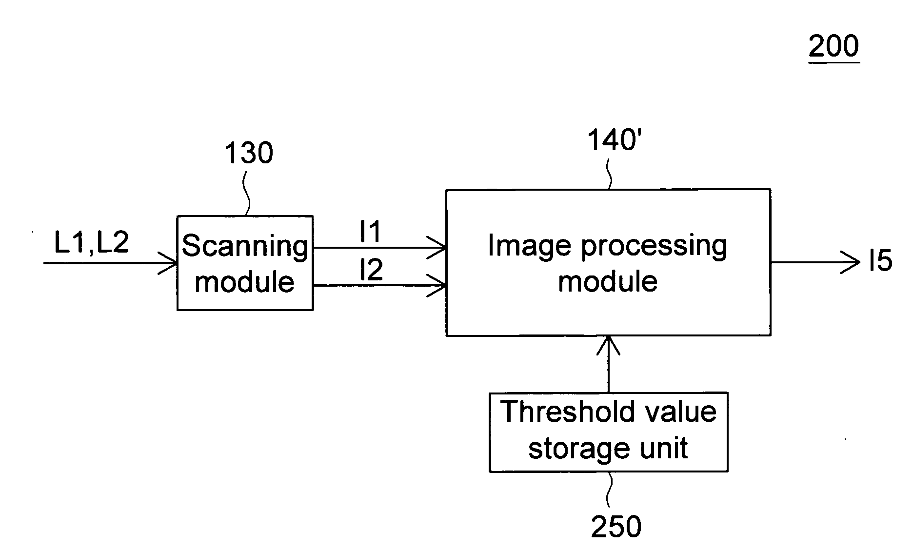
[0038]Referring to FIG. 11, a part of detailed block diagram of an image processing device according to a second embodiment of the invention is shown. The image processing method and the device using the same of the second embodiment differ with that of the first embodiment different in the method of obtaining the threshold value T, and other similarities are not repeated here.

[0039]Referring to FIG. 11, the image processing device 200 further has a threshold value storage unit 250 which records the threshold value T corresponding to different types of transparent manuscripts 102. In the present embodiment of the invention, the threshold value storage unit 250 stores the threshold value T of the transparent manuscript 102, and different types of transparent manuscripts 102 have different threshold values T.

[0040]Also, referring to FIG. 3 and FIG. 10. In step 403, the image processing module 140′ obtains a threshold value T from the threshold value storage unit 250 according to the t...


PUM


Abstract

An image processing method of removing flaw and a device using the same are provided. The image processing method is used in an image processing device and includes the following steps. Firstly, a transparent manuscript is transparently scanned to obtain a first scanning image. Next, the transparent manuscript is reflectively scanned to obtain a second scanning image. Then, a flaw-positioning image is obtained via the second scanning image. Afterwards, the first scanning image is modified by using the flaw-positioning image according to an image-recovered method for correcting the image value of the pixel in the first scanning image corresponding to at least part of the flaw in the transparent manuscript.

Description

[0001]This application claims the benefit of Taiwan application Serial No. 96144844, filed Nov. 26, 2007, the subject matter of which is incorporated herein by reference.BACKGROUND OF THE INVENTION[0002]1. Field of the Invention[0003]The invention relates in general to an image processing method and the device using the same, and more particularly to an image processing method of removing flaw and the device using the same.[0004]2. Description of the Related Art[0005]With the popularity of information digitalization, nowadays most of the images, films and photos are stored in digital formats. Meanwhile, the scanner further converts the images, films and photos from non-digital format into digital format. If information is stored in a non-digital format, then scratch, dust or shear marks may easily occur especially on the films. The most popular technology used in a scanner for removing film scratch is infrared scratch removing technology. The method recognizes the position of dust o...

Claims


Application Information

Patent Timeline
Patent Type & Authority Applications(United States)
IPC IPC(8): G06K9/40G06K9/00H04N1/04
CPCG06K2209/19G06T5/005G06T5/50G06T2207/10008H04N2201/042H04N1/4097H04N2201/0404H04N2201/0418G06T2207/10152G06V2201/06G06T5/77
Inventor LI, LI-CAO
Owner QUISDA CORP
Learn More