Magnetic tape head

a magnetic tape and head element technology, applied in the field of magnetic tape head, can solve the problems of eroded head element portion, abrasion residue of magnetic tape and other dust, etc., and achieve the effect of improving playback and recording precision

Inactive Publication Date: 2009-05-28
TDK CORPARATION
View PDF18 Cites 24 Cited by
  • Summary
  • Abstract
  • Description
  • Claims
  • Application Information

AI Technical Summary

Benefits of technology

[0018]By means of the above abrading, the traveling surface of the magnetic tape becomes smooth, and moreover a portion of the protective film remains on the tape bearing surface, so that the tape bearing surface is protect

Problems solved by technology

However, if the magnetic tape is abraded due to travel, abrasion residue of the magnetic tape and other dust occurs.
This dust may remain in the head element portion, and so there is the problem that the h

Method used


Image

  • Magnetic tape head
  • Magnetic tape head
  • Magnetic tape head

Examples


Embodiment Construction

[0031]Below, the magnetic tape head of an aspect is explained. The same symbols are used to indicate the same elements, and redundant explanations are omitted.

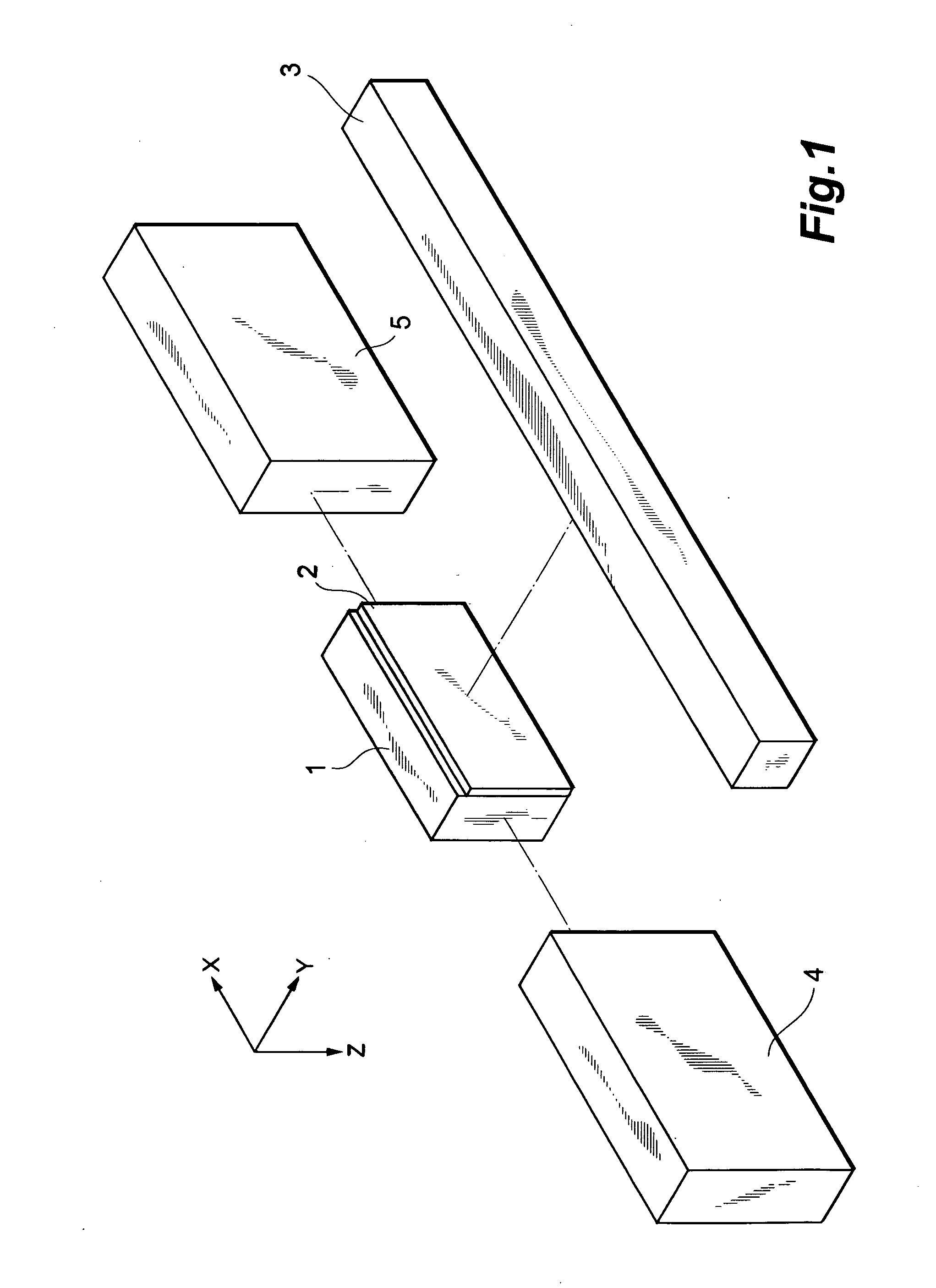
[0032]FIG. 1 is an exploded perspective view of a magnetic tape head intermediate member.

[0033]First, a magnetic head bar (chip), comprising a thin film magnetic head layer 2 formed on a base substrate 1, is prepared. The base substrate 1, closure piece 3, and bar end blocks 4, 5 each comprise AlTiC (Al2O3.TiO2), a ceramic (CaTiO3 or similar), or another high-hardness metal or other nonmagnetic material.

[0034]Here, an XYZ orthogonal coordinate system is set as shown in the figure. The thickness direction of the base substrate 1 and magnetic head layer 2 is the Y-axis direction, the length direction of the closure piece 3 is the X-axis direction, and the direction perpendicular to the XY plane is the Z-axis direction.

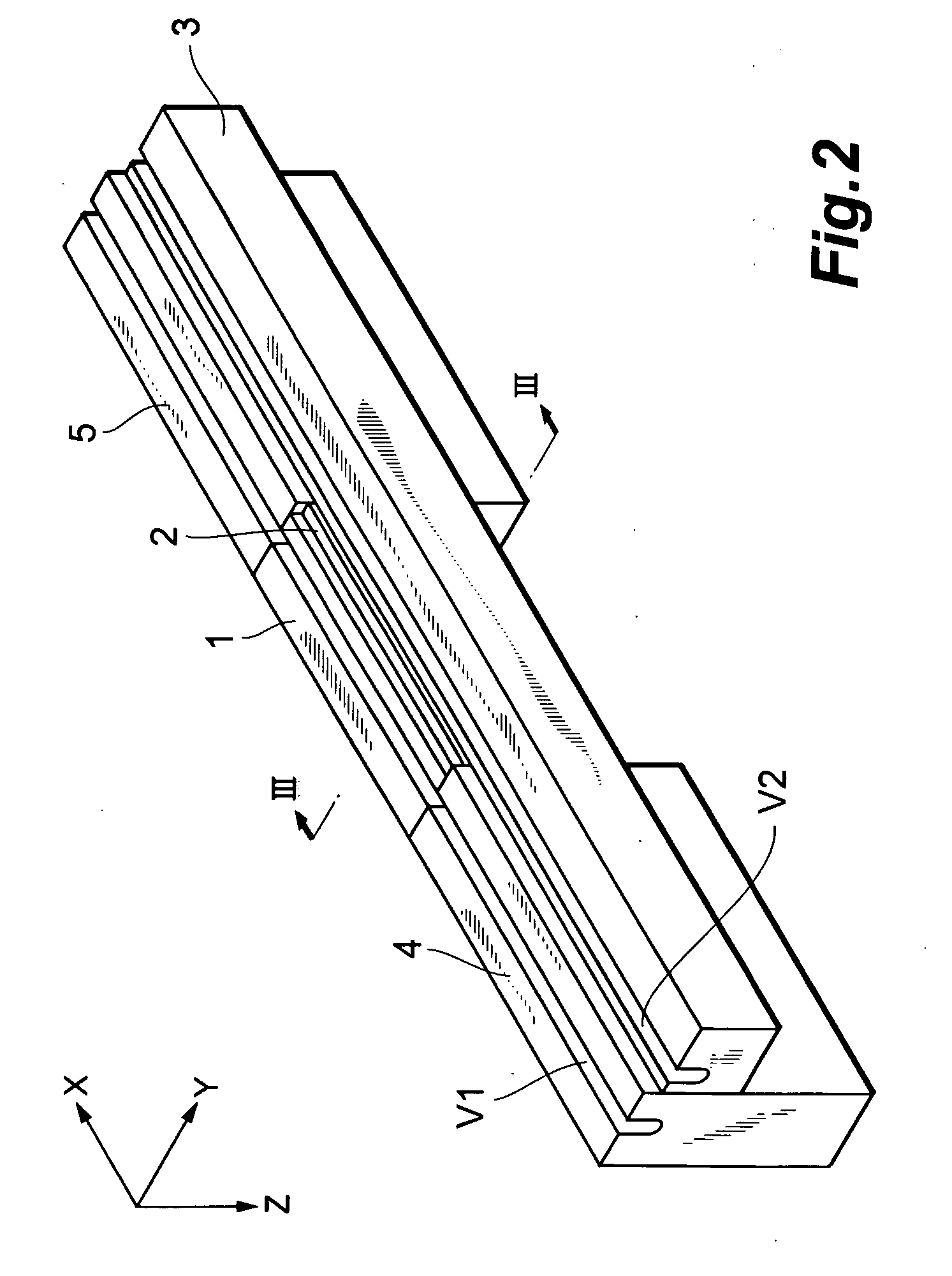
[0035]The closure piece 3 is positioned on the magnetic head layer 2 of the magnetic head bar, and the bar end b...


PUM


Abstract

A magnetic tape head has a base substrate, a magnetic head layer formed on the base substrate, and a closure piece formed on the magnetic head layer. The distance from a first plane comprising a point on the tape bearing surface of the base substrate to a third plane comprising a point on the tape bearing surface of the closure piece is equal to or greater than the distance from the first plane to a second plane comprising a point on the tape bearing surface of the magnetic head layer.

Description

BACKGROUND OF THE INVENTION[0001]1. Field of the Invention[0002]This invention relates to a magnetic tape head for use in tape head drives.[0003]2. Related Background Art[0004]Improvements in tape head drive performance in recent years have been accompanied by demands for improvements in magnetic tape head performance. To this end, hybrid thin film magnetic heads, comprising recording heads having inductive-type electromagnetic transducing elements and playback heads having magnetoresistance (MR) elements for reading, have come into widespread use.[0005]Magnetic tape heads of the prior art are for example disclosed in Japanese Patent Laid-open No. 2005-259198, Japanese Patent Laid-open No. 2003-203321, Japanese Patent Laid-open No. 2003-288710, Japanese Patent Laid-open No. 2001-118220, Japanese Patent Laid-open No. 07-153217, Japanese Patent Laid-open No. 11-353631, and U.S. Pat. No. 6,879,470.[0006]FIG. 12 is a cross-sectional view of such a magnetic tape head of the prior art.[00...

Claims


Application Information

Patent Timeline
IPC IPC(8): G11B5/127G11B5/187
CPCG11B5/00813G11B5/3106G11B5/1871
Inventor HACHISUKA, NOZOMU
Owner TDK CORPARATION
Why Eureka
Try Eureka