Flexible material flooring miter device and system for flexible material flooring installation

a technology of flexible flooring and miter devices, which is applied in the field of flexible flooring installation, can solve the problems of failing to provide an improved system and method for installing flash coving and creating precision flash coving seams, and failing to aid installers in creating miter joints of flash coving at the intersection of walls, so as to reduce the likelihood of user injury, prevent utility knife slippage, and accurate cut of flexible flooring

Inactive Publication Date: 2009-06-04
HERBERT ROBERT R +1
View PDF14 Cites 5 Cited by
  • Summary
  • Abstract
  • Description
  • Claims
  • Application Information

AI Technical Summary

Benefits of technology

[0029]In view of the foregoing disadvantages inherent in the known and various flexible flooring installation systems and devices now disclosed in the prior art, in accordance with a first preferred embodiment of the present invention, provided is a flash coving installation guide device for aiding an installer to make proper flash coving cuts and seams. More specifically, the first preferred embodiment is designed to be utilized to control and ultimately eliminate extensive damage to products and injuries to installers common with creating flash coving in flooring devices.
[0030]The primary purpose of the present invention, which will be described subsequently in greater detail, is to provide a first preferred embodiment concerning a guide tool for concise and proper cuts in flexible flooring to allow for the creation of proper seams in flash coving. The present invention is directed to a trim corner guide manufactured in a first right hand trim corner guide and a second left hand trim corner device. The devices are manufactured of sufficient material to act as a guide for a utility knife while cutting flexible flooring and are of sufficient thickness to allow the knife to extend beyond the guide.
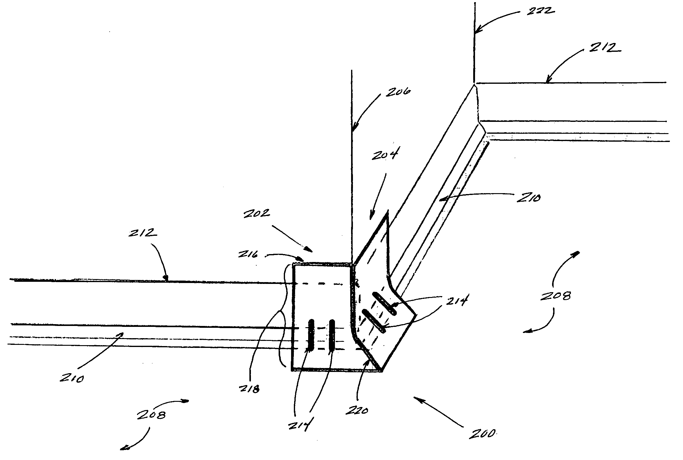
[0031]The hand-operated left hand trim corner guide is manufactured from a single piece of sturdy plastic material and is composed of a lower base having an upper surface and an underside adapted for contact with a flooring surface integrated with a curved cove forming portion angled to form an approximate ninety degree angle adapted to press the flooring surface into the subfloor and wall at or about an inside or outside corner. Due to inconsistencies in construction, in the preferred embodiment, this angle is increased to roughly ninety-five degrees as to allow the user to apply sufficient pressure to bend the guide to the approximate wall / floor angle and securely hold guide in place. The curved cove forming portion is further integrated with an upper portion of sufficient height to press flooring material against wall. Further integrated with the guide are guide post members allowing the installer to hold the guide in place and apply pressure to guide as to minimize movement of the guide during the cutting process. The left portion of guide is generally manufactured as a straight-edge while the right miter edge portion of guide is manufactured at a forty-five degree angle to allow for an angled miter cut at intersection of flooring material so as to create an aligned seam when installing flash coving.
[0036]It is therefore an object of the present invention to provide a system and method for providing accurate mitered cuts for the installation of flexible flooring.
[0037]One further object of the present invention is to provide a system and method which provides for a safe means for installing flash coving and allows for accurate cuts in flexible flooring while preventing utility knife slippage so as to reduce the likelihood of user injury.

Problems solved by technology

While the aforementioned inventions are directed to various improvements in the art for installing flexible flooring, each invention fails to provide an improved system and method for installing flash coving and creating precision flash coving seams.
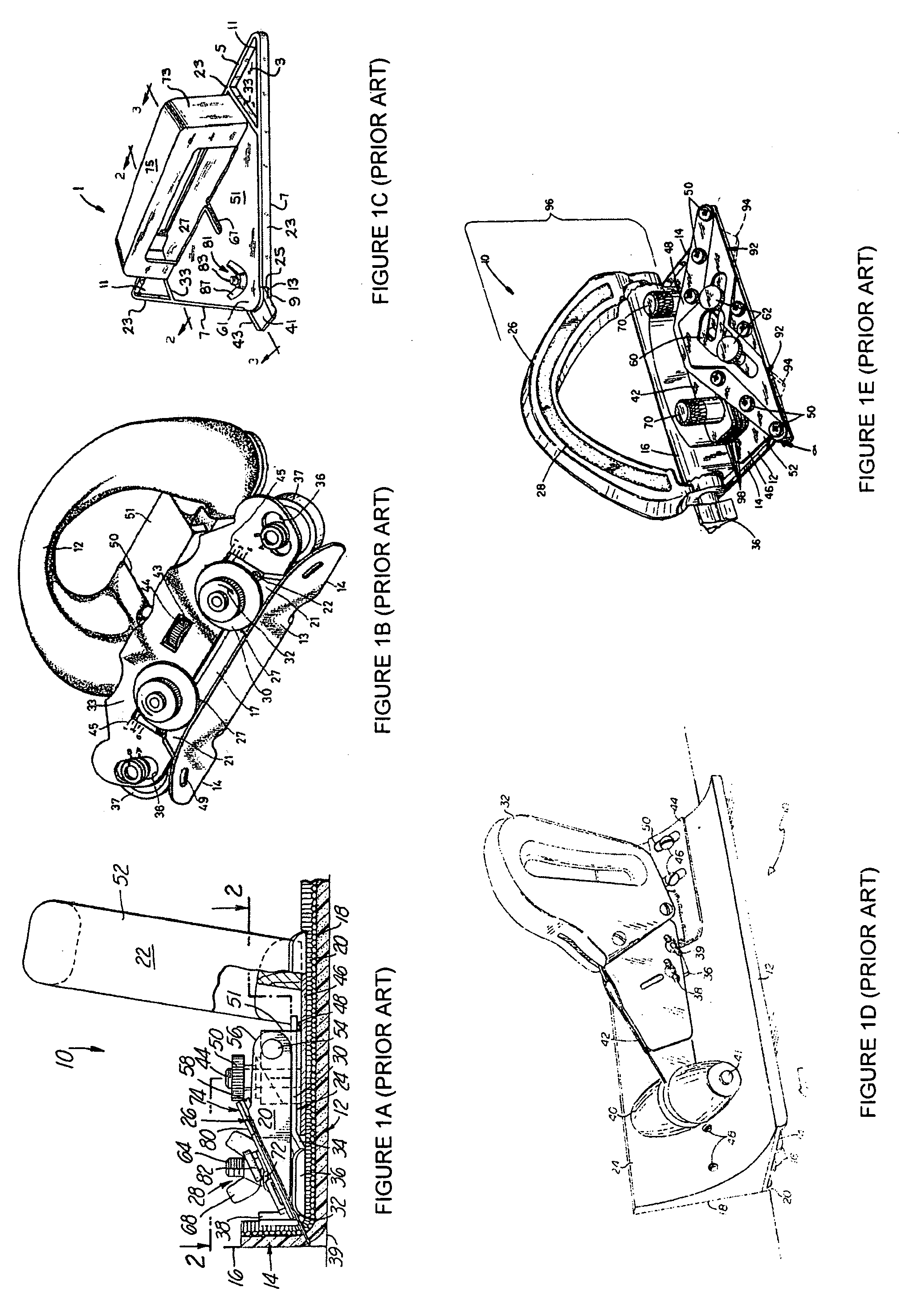
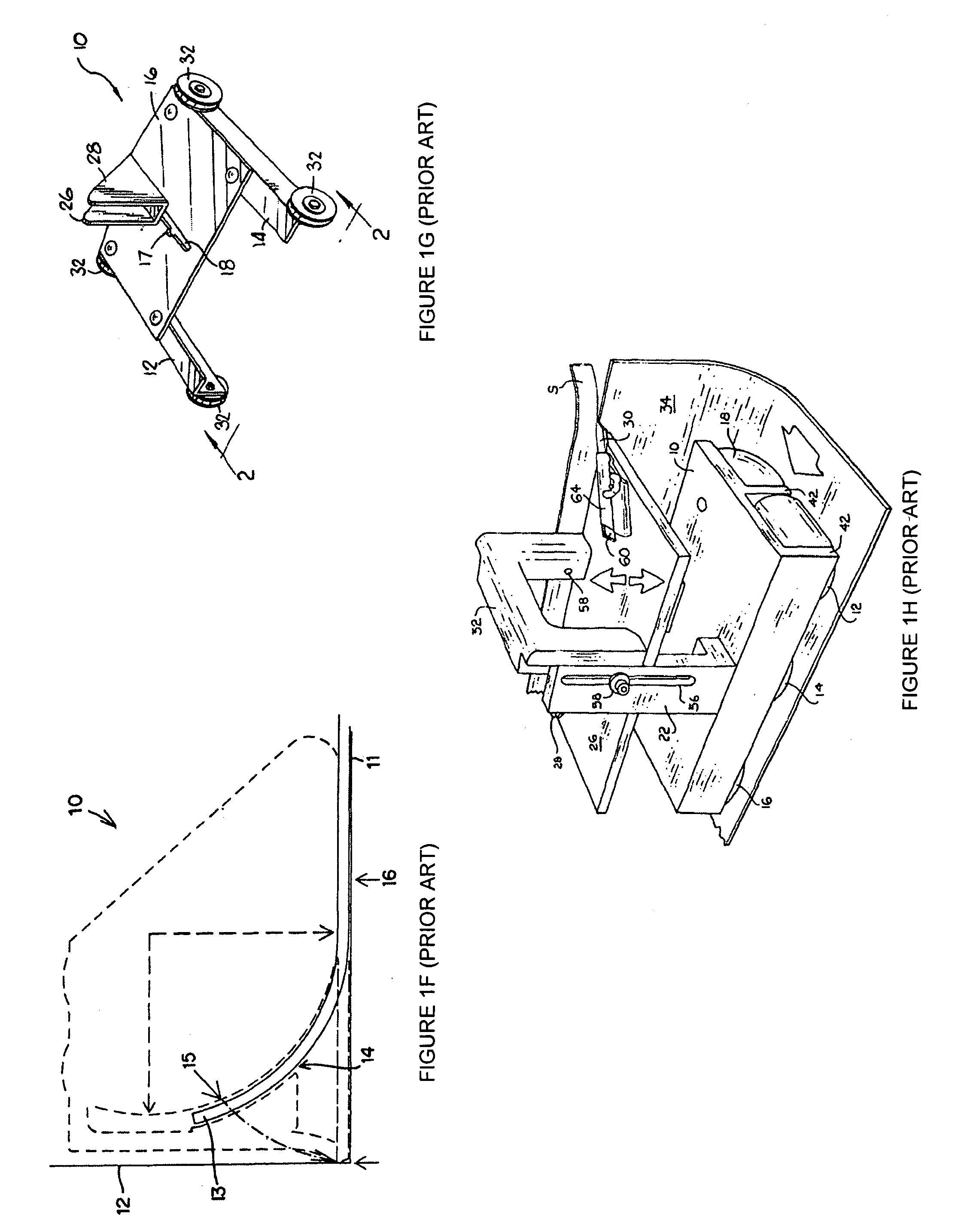
While arguably a useful development in the art, this device fails to aid an installer in creating miter joints of the flash coving at the intersection of the wall and floor

Method used


Image

  • Flexible material flooring miter device and system for flexible material flooring installation
  • Flexible material flooring miter device and system for flexible material flooring installation
  • Flexible material flooring miter device and system for flexible material flooring installation

Examples


Embodiment Construction

[0055]A detailed illustrative embodiment of the present invention is disclosed herein. However, techniques, systems and operating structures in accordance with the present invention may be embodied in a wide variety of forms and modes, some of which may be quite different from those in the disclosed embodiment. Consequently, the specific structural and functional details disclosed herein are merely representative, yet in that regard, they are deemed to afford the best embodiment for purposes of disclosure and to provide a basis for the claims herein which define the scope of the present invention. The following presents a detailed description of a preferred embodiment (as well as some alternative embodiments) of the present invention.

[0056]Moreover, well known methods, procedures, and substances for both carrying out the objectives of the present invention and illustrating the preferred embodiment are incorporated herein but have not been described in detail as not to unnecessarily ...


PUM


Abstract

A device and method for the proper installation of flexible flooring such as sheet flooring and more particularly the formation of flash coving and proper installation thereof comprising two complementary portions of a guide tool of proper angles and straightedges required to form mitered corner formation and installation.

Description

FIELD OF THE INVENTION[0001]The present invention generally relates to the field of flexible flooring installation. More specifically, the present invention relates to a device and method for the proper installation of flexible flooring such as sheet flooring and more particularly the formation of flash coving and proper installation thereof.BACKGROUND OF THE INVENTION[0002]Flexible flooring is commonly utilized as flooring cover in residential and commercial building. Depending on the intended use of a residential or commercial facility, various flooring options are available to the consumer. For example, residential and commercial linoleum, sheet vinyl floor coverings, glue down carpet products and other carpet products including rubber or vinyl backed carpets are commonly utilized in the art.[0003]In fact, the desire to provide floor coverings exhibiting a hard, relatively waterproof surface for shielding the foundations and supporting structures from the daily grind of activitie...

Claims


Application Information

Patent Timeline
Patent Type & Authority Applications(United States)
IPC IPC(8): E04F21/00E04F19/04
CPCA47G27/0487E04F21/00E04F15/16B26B29/06
Inventor HERBERT, ROBERT R.FOSTER, ERNEST D.
Owner HERBERT ROBERT R
Why Eureka
Try Eureka