Hydraulic inerter mechanism

a technology of inerter mechanism and mass element, which is applied in the direction of fluid coupling, clutch, coupling, etc., can solve the problems of limiting the freedom or flexibility of electro-mechanical system design, limiting the achievable performance of passive mechanical network, and reducing backlash problems, so as to reduce backlash and high external load , the effect of low cos

Inactive Publication Date: 2009-06-04
NAT TAIWAN UNIV
View PDF4 Cites 41 Cited by
  • Summary
  • Abstract
  • Description
  • Claims
  • Application Information

AI Technical Summary

Benefits of technology

[0011]In light of the shortcomings of the above prior arts, it is an objective of the invention to provide a hydraulic inerter mechanism for enhancing the correspondence between electrical networks and mechanical networks.
[0013]It is another objective of the invention to provide a hydraulic inerter mechanism that can be assembled at low cost.
[0017]The use of hydraulic cylinders can sustain high external loads, and reduce backlash problems. Moreover, since the use of hydraulic cylinders is a well-known and well-developed technique in the industry, it is feasible to provide a low cost inerter mechanism to replace the gear mechanism of the prior art.
[0018]In addition, a vibration control system usually consists of damping components for dissipating energy. The hydraulic inerter mechanism of the invention provides damping effects, and thus can avoid adding such components. In summary, compared with the prior arts, the inerter mechanism of the invention can provide ideal inerter characteristics in a vibration system with high external loads and a high damping coefficient.

Problems solved by technology

However, the mass element fails to be a genuine two-terminal network element in that one terminal of the mass is always connected to the ground.
Nevertheless, this requirement limits the freedom or flexibility in designing electro-mechanical systems.
However, the imperfect analogy of mass elements has limited the achievable performance of passive mechanical networks.
Although a rack-and-pinion inerter mechanism is easy to design and its materials are readily available, the backlash between gears might be serious.
The backlash problem refers to two adjoint gears being temporarily incapable of effectively meshing with each other such that the two gears are not in effective contact with each other during rotation.
For example, when the gears switch the direction of motion at high speed, backlash between gears will cause system delay or phase lag.
Moreover, the gears of a rack-and-pinion inerter are likely to collapse when the mechanism is under large external load.

Method used


Image

  • Hydraulic inerter mechanism
  • Hydraulic inerter mechanism
  • Hydraulic inerter mechanism

Examples


first embodiment

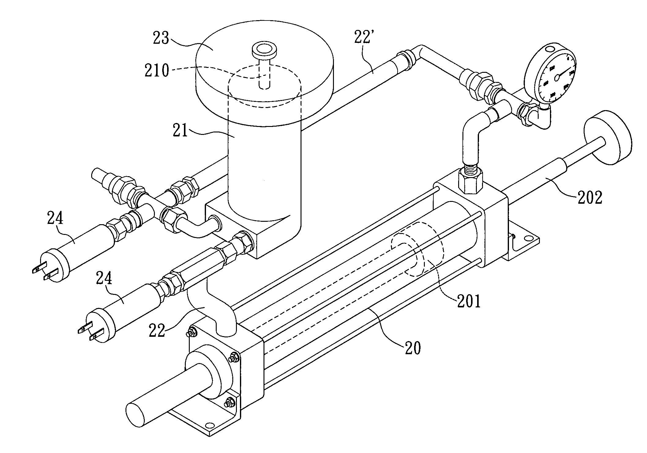
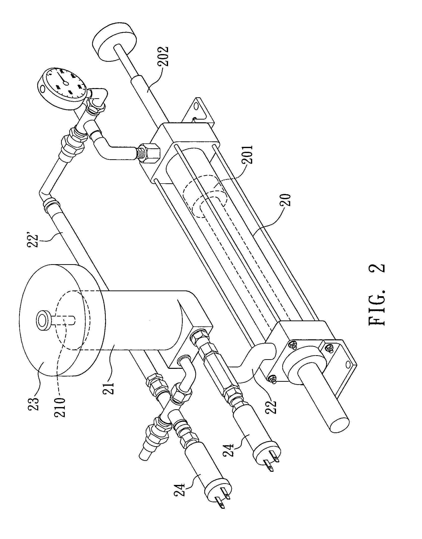
[0026]Referring to FIGS. 2 and 3, the invention provides a hydraulic inerter mechanism, comprising a hydraulic cylinder 20, a hydraulic motor 21 and an inertia body 23. The hydraulic cylinder 20 includes a piston 201 disposed inside the cylinder and a piston rod 202 connected therewith and emerging externally, wherein the piston 201 divides the hydraulic cylinder 20 into two compartments 203 and 203′, in which each compartment has a respective joint openings 204. The hydraulic motor 21 includes an output shaft 210, an inlet 211 and an outlet 212, wherein the inlet 211 and the outlet 212 are connected to the joint openings 204 of the hydraulic cylinder 20 through pipe bodies 22 and 22′, respectively. The inertia body 23 is preferably a flywheel and disposed on the output shaft 210.

[0027]In addition, the hydraulic cylinder 20 and hydraulic motor 21 include working fluid therein, as well as manometers 24 connected to the pipe bodies 22 and 22′. The manometers are used to measure pressu...

second embodiment

[0034]Referring to FIG. 4, the embodiment differs from the first embodiment only in the connection between the output shaft 210 and the inertia body 23. The other parts of design of the hydraulic inerter mechanism, such as the hydraulic cylinder 20, the hydraulic motor 21, the pipe bodies 22 and 22′ and the manometers 24, are substantially or completely the same, and therefore the followings are descriptions of the differentiated features only.

[0035]As shown in FIG. 4, the inertia body 23 is disposed and fixed onto a gear box 40 with gear set therein (not shown in the figure). One end of the gear box 40 is externally connected to the inertia body 23, and the other end is externally connected to a drive gear 41. An initiative gear 42 is disposed and fixed onto the output shaft 210 of the hydraulic motor 21. The drive gear 41 and the initiative gear 42 are in mesh, thereby forming a mechanical connection between the output shaft 210 and the inertia body 23. When the hydraulic motor 21...

third embodiment

[0038]Referring to FIG. 5, the only difference between the embodiment and the first embodiment is the modification of the structure of the inertia body 23. The other parts of the design of hydraulic inerter mechanism, such as the hydraulic cylinder 20, the hydraulic motor 21, the pipe bodies 22 and 22′, and the manometers 24 are mostly or completely the same as in the first embodiment, and, therefore the following descriptions are of the differing features only.

[0039]As shown in FIG. 5, the inertia body 23 has at least a mass block 50 therein. The mass block 50 is used to adjust the moment of inertia of the inertia body 23 disposed and fixed onto the output shaft 210 of the hydraulic motor 21. When the hydraulic motor 21 drives the output shaft 210, it simultaneously drives the inertia body 23 to revolve. Therefore, by adding in at least a mass block 50 to adjust the moment of inertia of the inertia body 23, the inertance of the hydraulic inerter mechanism is adjusted accordingly.

[0...


PUM


Abstract

The invention provides a hydraulic inerter mechanism, including: a hydraulic cylinder; a hydraulic motor connected to the hydraulic cylinder, with an output shaft thereon for converting the motion of the hydraulic cylinder from rectilinear motion to rotary motion; and an inertia body disposed on the output shaft. In operation, an external force applied to the inerter mechanism causes displacement of the piston, thereby pushing working fluid inside the hydraulic cylinder to generate a pressure difference between an inlet and an outlet of a hydraulic motor. The differential pressure consequently drives the hydraulic motor to rotate, and then the output shaft further drives the inertia body to rotate, thereby attaining inerter characteristics.

Description

BACKGROUND OF THE INVENTION[0001]1. Field of the Invention[0002]This invention generally relates to inerter mechanisms, and, more specifically, to a hydraulic inerter mechanism.[0003]2. Description of Related Art[0004]Electro-mechanical system integration has become one of the most important areas of engineering field in the 21st century. In such integration, it is often necessary to convert electrical characteristics into mechanical characteristics, or vice-versa. In conventional engineering applications, there are two analogies between the mechanical and electrical systems, namely the “force-current” analogy and the “force-voltage” analogy. For the force-current analogy, the physical characteristics of mass, damping and spring correspond to the electrical characteristics of capacitance, resistance and inductance, respectively. Also, for the force-voltage analogy, the physical characteristics of mass, damping, and spring correspond to the electrical characteristics of inductance, r...

Claims


Application Information

Patent Timeline
Patent Type & Authority Applications(United States)
IPC IPC(8): F16D31/02
CPCF15B7/008
Inventor WANG, FU-CHENGLIN, TZ-CHIAN
Owner NAT TAIWAN UNIV
Why Eureka
Try Eureka