Device and Method for the Material Testing and/or Thickness Measurements of a Test Object That Contains at Least Fractions of Electrically Conductive and Ferromagnetic Material

a technology of electrically conductive and ferromagnetic materials, which is applied in the direction of analysing solids using sonic/ultrasonic/infrasonic waves, using reradiation, and fluid analysis using sonic/ultrasonic/infrasonic waves, etc., to achieve the effect of reducing the force density induced within the test object in order to generate ultrasonic waves and short service life of emus-transducers that should

Inactive Publication Date: 2009-06-04
FRAUNHOFER GESELLSCHAFT ZUR FOERDERUNG DER ANGEWANDTEN FORSCHUNG EV
View PDF6 Cites 28 Cited by
  • Summary
  • Abstract
  • Description
  • Claims
  • Application Information

AI Technical Summary

Benefits of technology

[0019]Consequently, a resultant magnetic field that either results from the addition or the subtraction of both magnetic field intensities is formed within the region in which both magnetic fields are superimposed, namely in dependence on the orientation of the periodically changing direction of the magnetic field lines of the alternating field. Pressure waves are induced due to the magnetostrictive effect of the periodically changing resultant magnetic field within the test object, wherein these pressure waves cause the release of free ultrasonic waves that propagate within the test object perpendicular to the engineered surface. In addition, Lorentz forces are generated by the eddy currents induced in the test object and act in the region of the tangential magnetic field, wherein these Lorentz forces also generate pressure waves for the formation of free ultrasonic waves, the propagating direction of which is oriented perpendicular to the engineered surface. In the above-described constellation between the conventional magnetic field generated by the permanent or electromagnetic assembly and the eddy currents that can be generated with the eddy current coil, both effects contribute to the generation of free ultrasonic waves that are used for measuring and accordingly inspecting a test object over its entire depth.

Problems solved by technology

When examining ferromagnetic test objects, this is further complicated, in particular, in that the eddy current coil situated between the permanent magnet and the test object is literally pressed onto the surface of the test object due to the attractive effect of the magnetic forces and thusly subjected to significant frictional wear.
The above-described frictional wear as well as the additional impact stress on the electromagnetic ultrasonic transducer, particularly on the eddy current coil, results in short service lives of EMUS-transducers that should be extended.
Although it is possible to reduce the frictional wear by diminishing the magnetic forces of attraction acting between the EMUS-transducer and the test object to be examined, for example, by lowering the magnetic field induction, this measure would simultaneously result in a substantially lower efficiency of the EMUS-transducer, that is, the force density induced within the test object in order to generate the ultrasonic waves is reduced correspondingly such that the detection sensitivity during the reception of scattered or reflected ultrasonic waves is diminished accordingly.
Such ultrasonic waves that propagate parallel to the test object surface are well suited for the material testing near the surface, but cannot be used for depth or thickness measurements on the test objects.

Method used


Image

  • Device and Method for the Material Testing and/or Thickness Measurements of a Test Object That Contains at Least Fractions of Electrically Conductive and Ferromagnetic Material
  • Device and Method for the Material Testing and/or Thickness Measurements of a Test Object That Contains at Least Fractions of Electrically Conductive and Ferromagnetic Material
  • Device and Method for the Material Testing and/or Thickness Measurements of a Test Object That Contains at Least Fractions of Electrically Conductive and Ferromagnetic Material

Examples


Embodiment Construction

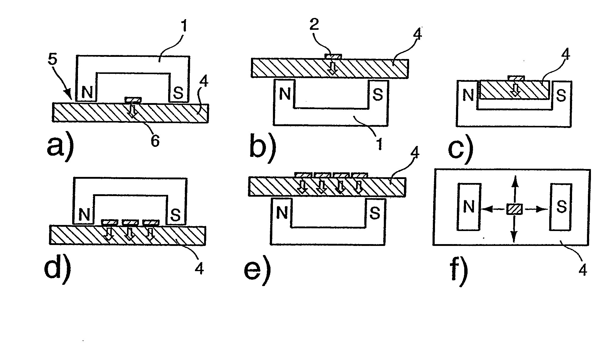
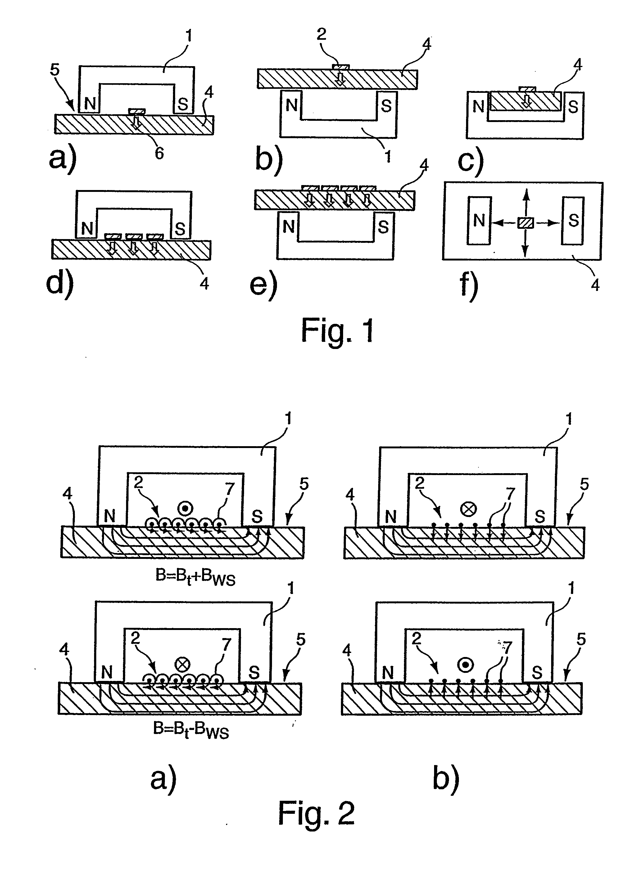
[0031]Different arrangements and configurations of the device in accordance with the invention are illustrated in FIGS. 1a to f. In order to test materials and, in particular, to measure the thickness of a test object 4 that consists of an electrically conductive and ferromagnetic material, the device features a U-shaped permanent magnet assembly 1 that spans over the test object 4 in a yoke-like fashion and directly contacts the engineered surface of the test object 4 on the face side with its magnetic poles N, S. As described further below, in particular, with reference to FIG. 2, the permanent magnet 1 induces a tangential magnetic field within the test object 4 in the region between the magnetic poles N, S, wherein this tangential magnetic field is constant over time if a permanent magnet 1 is used. Instead of providing the permanent magnet 1 illustrated in FIG. 1, it would also be possible to utilize an electromagnet of identical or similar configuration that is able to induce ...


PUM

PropertyMeasurementUnit
magnetic polarityaaaaaaaaaa
magnetic fieldaaaaaaaaaa
eddy current densityaaaaaaaaaa

Abstract

The invention relates to a device and a method for testing the material of a test object (4) which contains at least electrically conductive and ferromagnetic material fractions and has at least one engineered surface (5), by means of at least one electromagnetic ultrasonic transducer assembly (EMUS). Said assembly comprises a permanent or electromagnetic assembly (1) comprising at least two magnetic poles (N, S) of different magnetic polarity that face the engineered surface (5), in addition to an eddy current coil (2) that is placed in close proximity to the engineered surface (5) between the two magnetic poles (N, S) in indirect or direct relation to the engineered surface (5). The invention is characterized in that the eddy current coil (2) is configured and arranged in such a way that when said coil (2) is supplied with an alternating current, free ultrasonic waves that run essentially perpendicular to the engineered surface (5) are generated and propagate inside the test object (4).

Description

BACKGROUND OF THE INVENTION[0001]1. Field of the Invention[0002]The invention pertains to a device and a method for the material testing of a test object that contains at least fractions of electrically conductive and ferromagnetic material and features at least one engineered surface with at least one electromagnetic ultrasonic transducer assembly (EMUS) that comprises a permanent or electromagnetic assembly with at least two magnetic poles of different magnetic polarity that face the engineered surface, as well as at least one eddy current coil that is arranged in a projection on the engineered surface between the two magnetic poles in indirect or direct relation to the engineered surface.[0003]2. Description of the Prior Art[0004]It is common practice to utilize electromagnetic ultrasonic transducers for nondestructive material testing and for measuring test objects that consist of electrically conductive materials and preferably also have ferromagnetic properties.[0005]One can d...

Claims


Application Information

Patent Timeline
Patent Type & Authority Applications(United States)
IPC IPC(8): G01N29/24G01N27/90
CPCB06B1/04G01N27/9033G01N2291/051G01N2291/0422G01N2291/044G01N29/2412G01N27/9006
Inventor KRONING, MICHAELNICHIFORENCO, JORJBOULAVINOV, ANDREI
Owner FRAUNHOFER GESELLSCHAFT ZUR FOERDERUNG DER ANGEWANDTEN FORSCHUNG EV
Why Eureka
Try Eureka