Driving device and driving method of capacitive load and liquid jet printing apparatus

a technology of capacitive load and driving device, which is applied in the direction of pulse generator, pulse technique, instruments, etc., can solve the problems of large heat sink, substantial power loss, and further power loss, and achieve the effect of avoiding the power loss caused by the damping resistor

Active Publication Date: 2009-06-04
SEIKO EPSON CORP
View PDF2 Cites 41 Cited by
  • Summary
  • Abstract
  • Description
  • Claims
  • Application Information

AI Technical Summary

Benefits of technology

[0024]According to the driving method of a capacitive load of this aspect of the invention, since the characteristic variation caused when performing the power amplification using the digital power amplifier can be suppressed or prevented and further, the frequency characteristic of the passing band of the drive signal thus output can be planarized without using the damping resistor by keeping the sum of the capacitance of the load capacitors and the capacitance of the dummy load capacitors connected to the inductor within a predetermined range, the power loss caused by the damping resistor can be avoided.

Problems solved by technology

Incidentally, in the liquid jet printing apparatus of this kind, the drive signal amplified by a power amplifying circuit is applied to a nozzle actuator such as a piezoelectric element to emit a jet of a liquid from a nozzle, and if the drive signal is amplified by an analog power amplifier such as a linearly driven push-pull connected transistor, a substantial power loss is caused, and a large heat sink is required.
Further, in order for suppressing the resonance of the filter, a damping resistor is usually inserted between the inductor and the load capacitor, and the damping resistor causes a further power loss.

Method used


Image

  • Driving device and driving method of capacitive load and liquid jet printing apparatus
  • Driving device and driving method of capacitive load and liquid jet printing apparatus
  • Driving device and driving method of capacitive load and liquid jet printing apparatus

Examples


first embodiment

[0040]A liquid jet printing apparatus using a driving device of a capacitive load as the invention will hereinafter be explained.

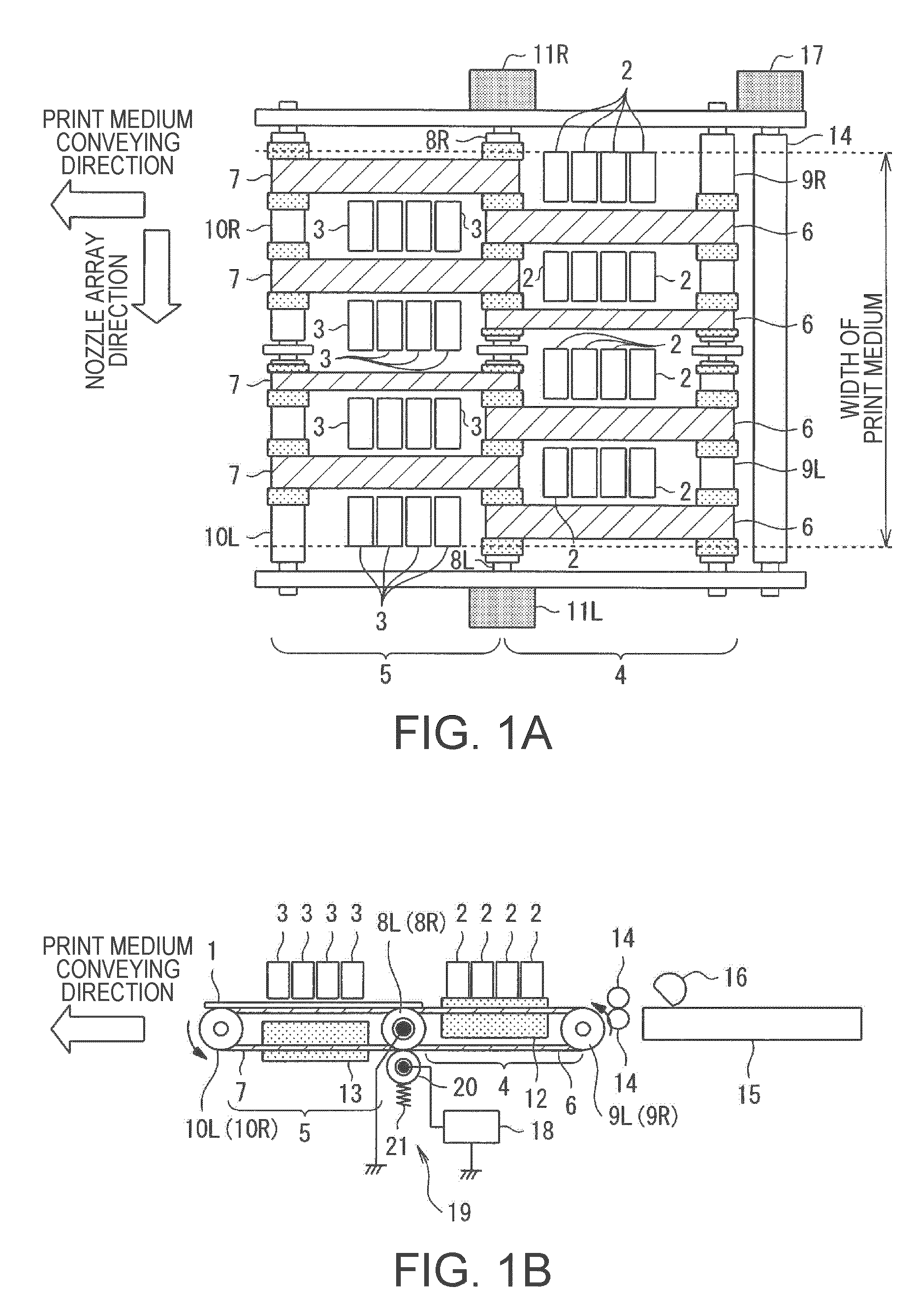
[0041]FIGS. 1A and 1B are schematic configuration diagrams of the liquid jet printing apparatus according to the first embodiment, wherein FIG. 1A is a plan view thereof, and FIG. 1B is a front view thereof. In FIGS. 1A and 1B, in a line head printing apparatus, a print medium 1 is conveyed from right to left of the drawing along the arrow direction, and is printed in a print area in the middle of the conveying path.

[0042]The reference numeral 2 in the drawing denotes first liquid jet heads disposed on the upstream side in the conveying direction of the print medium 1, the reference numeral 3 denotes second liquid jet heads disposed similarly on the downstream side, a first conveying section 4 for conveying the print medium 1 is disposed below the first liquid jet heads 2, and a second conveying section 5 is disposed below the second liquid jet heads 3. Th...

second embodiment

[0075]In the second embodiment, the dummy load capacitors 27 have different capacitance from that of the nozzle actuators 22. Specifically, the capacitance of each of the dummy load capacitor 27 is made corresponding to the capacitance of J nozzle actuators 22. Here, it is assumed that the total number M of the nozzle actuators 22 is 360, and the case in which the capacitance of each of the dummy load capacitors 27 corresponds to the capacitance of 90 (=J) nozzle actuators 22 will be explained.

[0076]The total number K of the dummy load capacitors 27 is obtained by dividing the total number M of the nozzle actuators 22 by J and further subtracting 1 therefrom, namely by the formula K=(M / J)−1, and in this case, K is obtained as 3. Further, the selection switch 23 is provided in correspondence with all of the capacitances of the nozzle actuators 22 and the dummy load capacitors 27. The selection switches 23 are each formed of a transmission gate or the like. The selection switches 23 a...

third embodiment

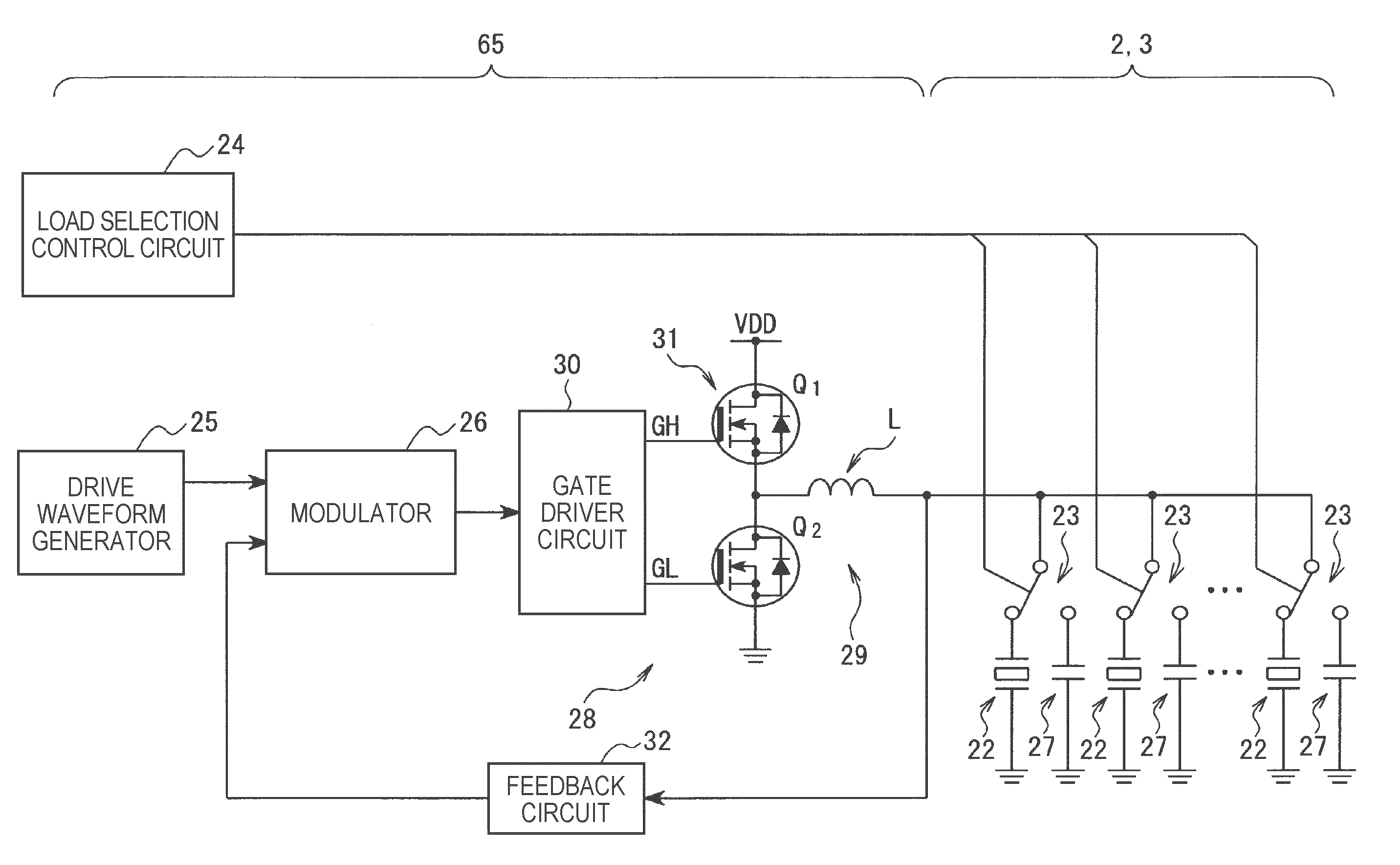
[0079]Hereinafter, as the driving device of a capacitive load applied to the liquid jet printing apparatus of the invention, FIG. 9 shows another example of a specific configuration of the head driver 65, the liquid jet heads 2, and the liquid jet heads 3. FIG. 9 includes a number of constituents identical to those of the configurations shown in FIGS. 4 and 7, and since those constituents essentially have substantially the same functions, the equivalent constituents are denoted with the equivalent numeral references, and the detailed explanation therefor will be omitted. The drive waveform signal generator 25, the modulator 26, the digital power amplifier 28, the low-pass filter 29 in the present embodiment have substantially the same functions as those shown in FIGS. 4 and 7, and the feedback circuit 32 having substantially the same function as that shown in FIG. 4 is adopted.

[0080]Further, also in the third embodiment, similarly to the case shown in FIG. 7, the dummy load capacito...


PUM


Abstract

A driving device of a capacitive load includes a modulator that executes pulse modulation on a drive waveform signal. An inductor performs low-pass filtering on the modulated drive waveform signal and outputs the low-pass filtered signal as a drive signal towards a load capacitor as the capacitive load. A load selection control circuit selects a load capacitor and a dummy load capacitor to be connected to the inductor so that a sum of the capacitances of the selected load capacitor and dummy load capacitor is kept within a predetermined range. A feedback circuit executes a filtering process on the drive signal so that a frequency characteristic of a passing band of the drive signal becomes substantially flat. The resulting signal is provided to the modulator as a feedback signal. The modulator executes the pulse modulation on a difference value between the drive waveform signal and the feedback signal.

Description

BACKGROUND[0001]1. Technical Field[0002]The present invention relates to a driving device and a driving method of a capacitive load formed of a load capacitor, and is particularly suitable for a liquid jet printing apparatus adapted to form a predetermined character or graphics by emitting a jet of a minute liquid to form a fine particle (dot) on a medium.[0003]2. Related Art[0004]An inkjet printer as one of such liquid jet printing apparatuses, which is generally low-price and easily provides high quality color prints, has widely been spreading not only to offices but also to general users along with widespread of personal computers or digital cameras.[0005]A device having a liquid jet head provided with a liquid jet nozzle and mounted on a moving member called a carriage to move in a direction intersecting with a conveying direction of a print medium is generally called “a multi-pass printing apparatus.” In contrast, a device having a liquid jet head elongated in a direction inter...

Claims


Application Information

Patent Timeline
Patent Type & Authority Applications(United States)
IPC IPC(8): H03K3/00
CPCB41J2/04541B41J2/04581B41J2/04588H03K7/08B41J2/04596H03F3/217B41J2/04593
Inventor MIYAZAKI, SHINICHIOSHIMA, ATSUSHIIDE, NORITAKATABATA, KUNIOAIZAWA, HIROYUKITANIGUCHI, SEIICHI
Owner SEIKO EPSON CORP
Why Eureka
Try Eureka