Reflective Display

a display and display technology, applied in the field of reflection display, can solve the problems of increased problems, unwanted absorption by those layers, and reduce efficiency, and achieve the effect of easy production

Active Publication Date: 2009-06-04
HEWLETT PACKARD DEV CO LP
View PDF15 Cites 37 Cited by
  • Summary
  • Abstract
  • Description
  • Claims
  • Application Information

AI Technical Summary

Benefits of technology

[0013]Reflective layers can be made easily, for example by use of curable cholesteric materials such as those from Merck.
[0014]A further benefit of this invention arises with the use of dichroic dyed layers as the controllable absorption layers. To absorb both polarizations in their absorbing orientation, prior art has suggested using a quarter-wave plate behind the layer, in order to convert the unabsorbed polarization into one which on reflection will be absorbed during the

Problems solved by technology

A problem with reflective displays is that light must pass through a number of layers twice, and unwanted absorption by those layers can

Method used


Image

  • Reflective Display
  • Reflective Display
  • Reflective Display

Examples


Embodiment Construction

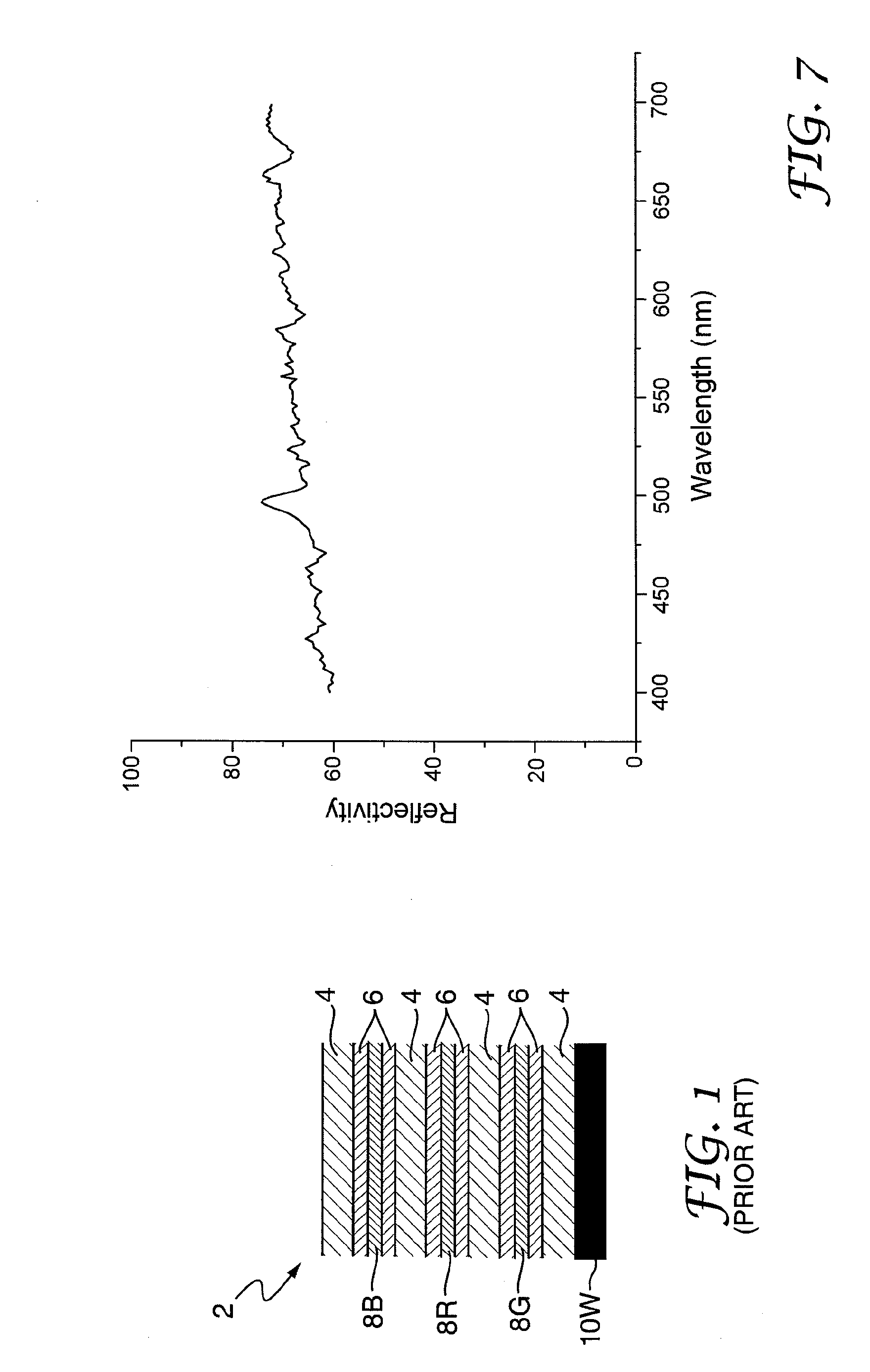
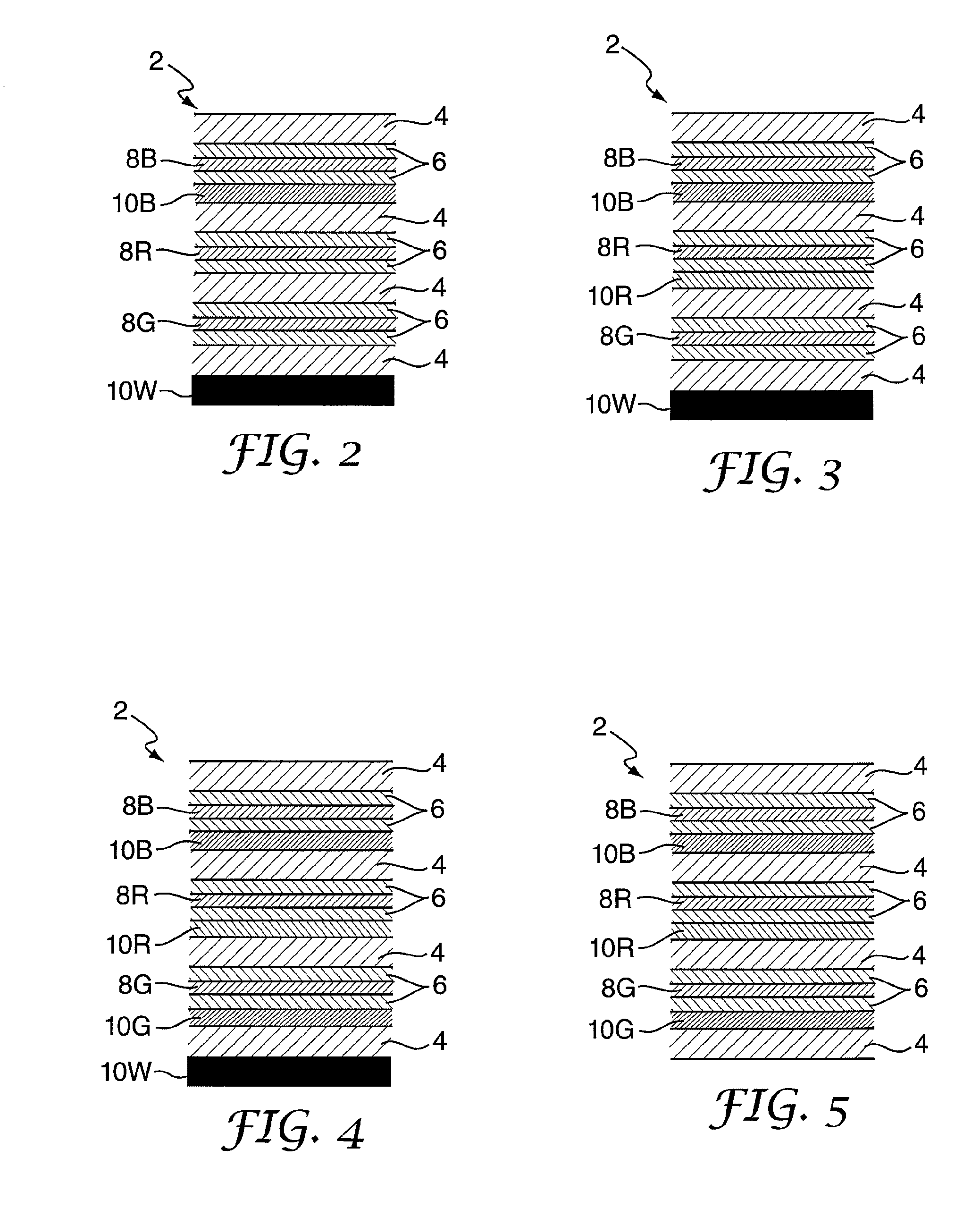
[0023]The prior art reflective display device 2 shown in FIG. 1 comprises a stack of selective absorption layers 8B, 8R and 8G, in this example liquid crystal layers 8, which can be made to absorb, respectively, blue, red and green light. The blue-absorbing layer 8B is at the top of the stack and the green-absorbing layer 8G is at the bottom of the stack.

[0024]Each absorption layer 8 is sandwiched between transparent substrates 4 and transparent conductors 6 and can be wholly or partly actuated by the application of suitable electric signals via the conductors 6. Thus selected pixel regions of each absorption layer 8 may be made either to absorb light in a particular wavelength band or substantially to transmit all incident light. A silver mirror 10W functions as a broadband reflector which reflects light of all wavelengths. The silver mirror 10W, is disposed at the bottom of the device 2 and reflects light back through the layers 4,6,8 to the viewer.

[0025]The light passes 12 times ...


PUM


Abstract

A reflective display device (2) comprises a plurality of controllable light absorption layers (8) arranged in a stack. Each of the layers (8) is capable of absorbing incident light in a specified wavelength band. A selective reflector (10) is immediately behind at least one of the layers (8) and is adapted to reflect at least some wavelengths of light within the wavelength band and substantially to transmit light of other wavelengths.

Description

[0001]The present invention relates to a reflective display, notably to a reflective full colour display.[0002]A reflective display is a non-emissive device in which ambient light for viewing the displayed information is reflected from the display back to the viewer rather than light from behind the display being transmitted through the display. A problem with reflective displays is that light must pass through a number of layers twice, and unwanted absorption by those layers can reduce efficiency. This problem is increased if a stack of controllable layers is used to allow independent control of different colours.SUMMARY OF THE INVENTION[0003]Aspects of the invention are specified in the independent claims. Preferred features are specified in the dependent claims.[0004]By putting a spectrally selective reflection layer immediately beneath a controllable absorption layer, any light in that spectral band not absorbed by the layer can be returned to the viewer without having to traver...

Claims


Application Information

Patent Timeline
IPC IPC(8): G09G3/34
CPCG02F1/133553G02F2203/34G02F2201/343G02F1/13473G02F1/1335G02F1/1347
Inventor GEISOW, ADRIANKITSON, STEPHEN
Owner HEWLETT PACKARD DEV CO LP
Why Eureka
Try Eureka