Projector

a projector and projector technology, applied in the field of projectors, can solve the problems of deterioration of the projected image quality, insufficient heat resistance of the light modulation device such as the liquid crystal panel in general, and the inability to achieve the effect of efficient cooling

Inactive Publication Date: 2009-06-04
SEIKO EPSON CORP
View PDF11 Cites 20 Cited by
  • Summary
  • Abstract
  • Description
  • Claims
  • Application Information

AI Technical Summary

Benefits of technology

[0026]According to this structure, the surface areas of the heat receiving side heat transfer member and the heat releasing side heat transfer member of the first heat exchanger are larger than those of the other heat exchanger. Thus, high-temperature air warmed by the optical component initially flows to the first heat exchanger. Thus, heat can be effectively absorbed from the high-temperature air, and air flowing through the flow path can be efficiently cooled step by step by the first heat exchanger.

Problems solved by technology

When dust, soot or the like adheres to the surface of the light modulation device of the projector, the quality of the projected image deteriorates.
Moreover, the light modulation device such as liquid crystal panel does not have sufficient heat resistance in general.
Thus, the light modulation device may be deteriorated by heat generated when light emitted from the light source device is applied thereto.
Thus, when the amount of heat generated from optical components contained in the closed unit is large, for example, it is difficult to efficiently cool the air inside the closed unit.
Thus, the optical components such as the light modulation device are difficult to be efficiently cooled.

Method used


Image

  • Projector
  • Projector
  • Projector

Examples


first embodiment

[0042]A first embodiment according to the invention is hereinafter described with reference to the drawings.

Structure of External Appearance

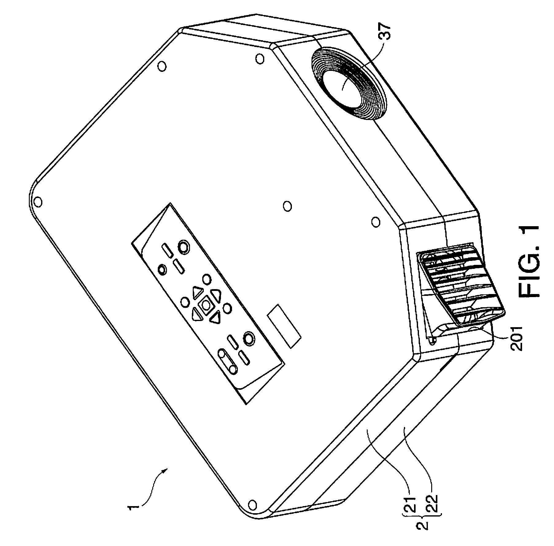
[0043]FIG. 1 is a perspective view illustrating an external appearance of a projector 1 in this embodiment. More specifically, FIG. 1 is a perspective view of the projector 1 as viewed from the upper front.

[0044]In the following description, it is assumed that the left direction in the figure corresponds to the left direction as viewed from the front of the projector 1, and that the right direction in the figure corresponds to the right direction as viewed from the front of the projector 1.

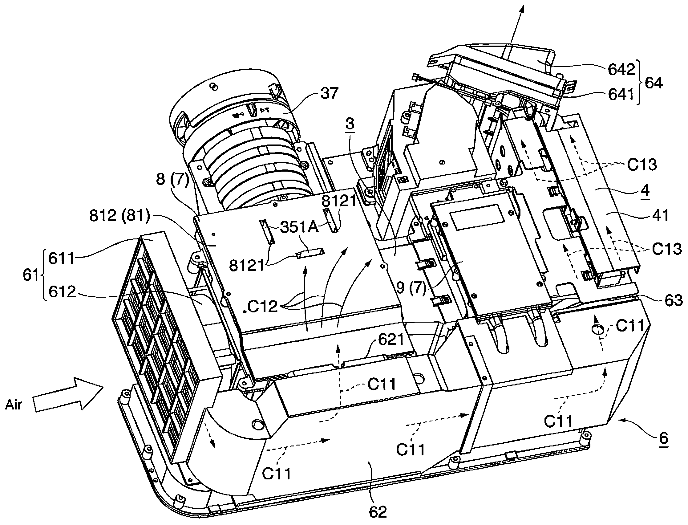
[0045]The projector 1 forms image light by modulating light emitted from a light source according to image information, and enlarges and projects the formed image light on a screen (not shown). The projector 1 has an external housing 2 constituting the external casing.

[0046]The external housing 2 is made of synthetic resin, and accommodates the main body of th...

second embodiment

[0176]A second embodiment according to the invention is now described with reference to the drawings.

[0177]Similar reference numbers are given to structures and parts similar to those in the first embodiment, and detailed explanation of those is not repeated or just briefly explained.

[0178]FIG. 14 is a perspective view illustrating disassembled structure of the heat exchanger 85 in the second embodiment. More specifically, FIG. 14 illustrates the heat exchanger 85 as viewed from the back.

[0179]According to the first embodiment, the respective heat receiving side heat transfer members 861 and 871 have the same shape, and the respective heat releasing side heat transfer members 863 and 873 have the same shape in the passive-type heat exchanger 86 and the active-type heat exchanger 87. That is, the surface area for receiving heat of air flowing through the flow path C32, and the surface area for releasing heat to air flowing through the flow path C11 in the passive-type heat exchanger ...


PUM


Abstract

A projector includes: an optical component disposed inside a closed structure having air flow path through which air flows; and a circulating fan which circulates air. The closed structure includes: an optical component housing which accommodates the optical component; a duct which introduces air into the optical component housing, and introduces the air having flowed to the outside from the inside of the optical component housing again toward the inside of the optical component housing; and a plurality of heat exchangers each of which has a heat receiving side heat transfer member which faces the inside of the closed structure, and a heat releasing side heat transfer member which faces the outside of the closed structure. The plural heat exchangers are disposed in the air flow direction along the air flow path through which air flows to the outside from the inside of the optical component housing.

Description

BACKGROUND[0001]1. Technical Field[0002]The present invention relates to a projector.[0003]2. Related Art[0004]Currently, such a projector is known which includes a light source device, a light modulation device for modulating light emitted from a light source device according to image information to form image light, and a projection system for enlarging and projecting the image light.[0005]When dust, soot or the like adheres to the surface of the light modulation device of the projector, the quality of the projected image deteriorates. Moreover, the light modulation device such as liquid crystal panel does not have sufficient heat resistance in general. Thus, the light modulation device may be deteriorated by heat generated when light emitted from the light source device is applied thereto.[0006]For overcoming these drawbacks, such a structure has been proposed which disposes the light modulation device within a closed unit and releases heat of air existing inside the closed unit ...

Claims


Application Information

Patent Timeline
Patent Type & Authority Applications(United States)
IPC IPC(8): G03B21/16
CPCG03B21/16
Inventor YANAGISAWA, YOSHIYUKIMOMOSE, YASUNAGA
Owner SEIKO EPSON CORP
Why Eureka
Try Eureka