
Phase error estimator, coherent receiver and phase error estimating method

a phase error estimation and coherent receiver technology, applied in the field of optical communication, can solve the problems of limiting the implementation and application of optical digital coherent receivers, the computational capability of currently available digital signal processing hardware, and the complexity of such multiplying computation is considerably higher than addition, subtraction and logical computations

Active Publication Date: 2009-06-04
FUJITSU LTD
View PDF6 Cites 9 Cited by
  • Summary
  • Abstract
  • Description
  • Claims
  • Application Information

AI Technical Summary

Benefits of technology

[0007]The present invention is proposed in view of the foregoing problems in the state of the art to solve one or more problems existed in prior art.

Problems solved by technology

From another point of view, the computational capability of currently available digital signal processing hardware also restricts the implementation and application of optical digital coherent receivers.
The complexity of such multiplying computation is considerably higher than addition, subtraction and logical computations.

Method used


Image

  • Phase error estimator, coherent receiver and phase error estimating method
  • Phase error estimator, coherent receiver and phase error estimating method
  • Phase error estimator, coherent receiver and phase error estimating method

Examples


Embodiment Construction

[0029]Specific embodiments of the present invention are described in greater detail below with reference to the accompanying drawings. These descriptions are exemplary and explanative in nature, rather than restrictive to the protection scope of the present invention.

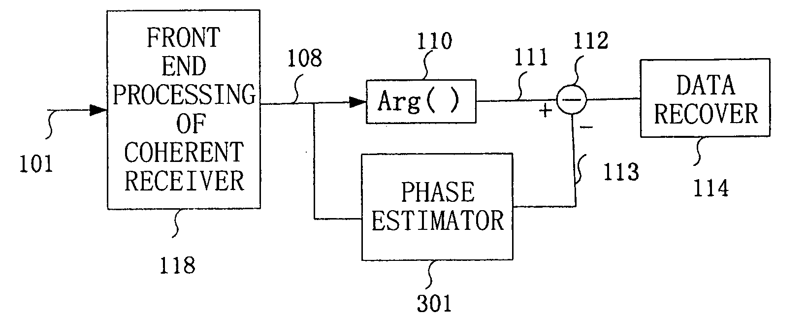
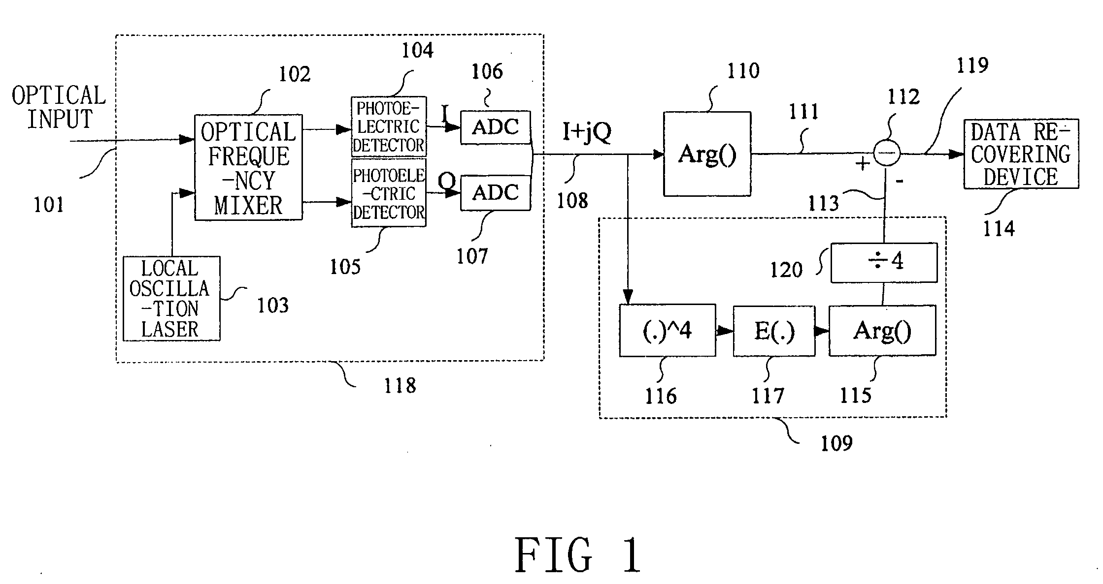
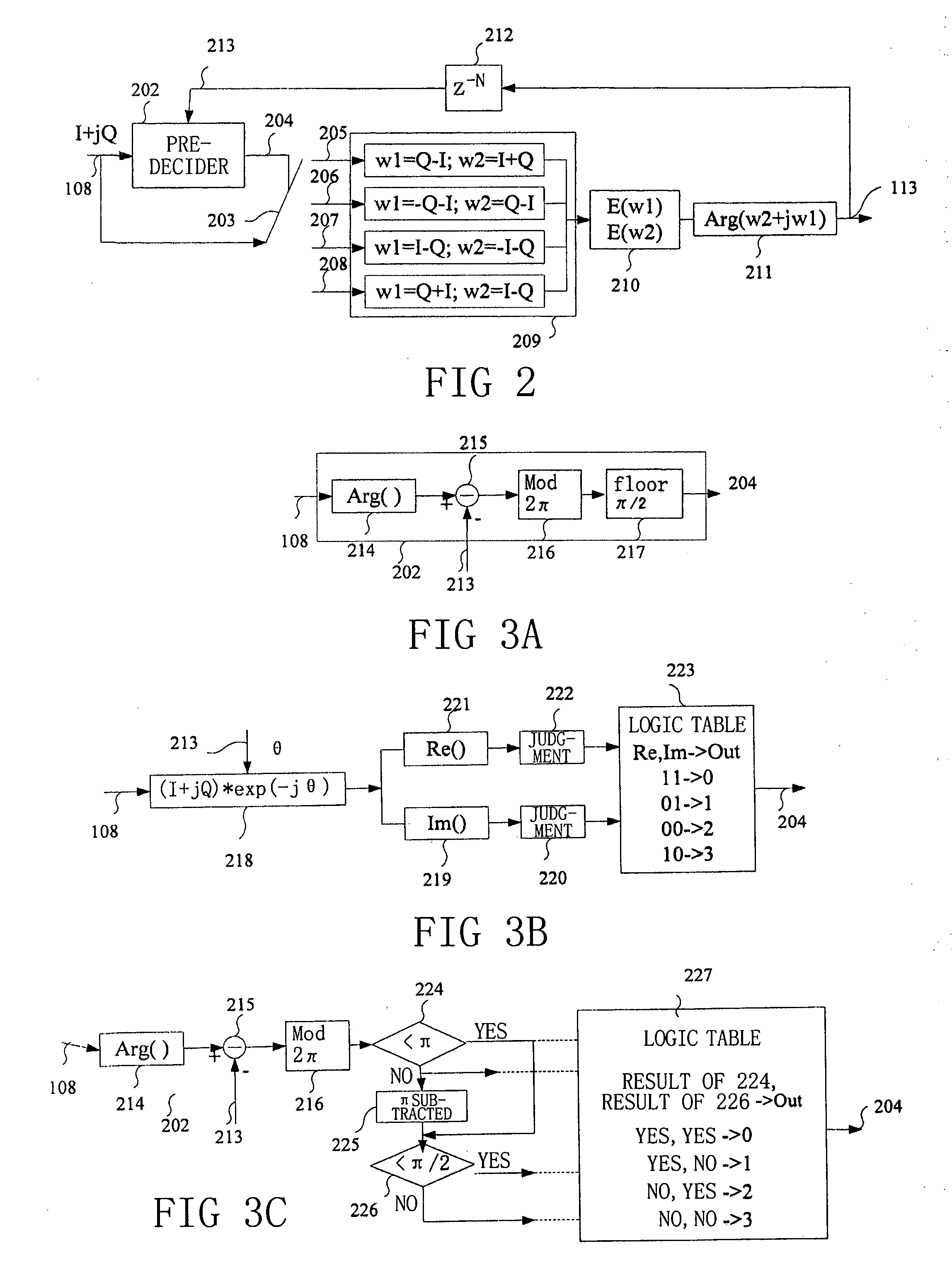
[0030]FIG. 2 illustrates the structure of the phase error estimator according to the present invention. The input of the phase error estimator is a base band electric signal 108, namely I+jQ=exp(jθd+jθ), that is outputted from the front end processing section 118 (see FIG. 1) of the coherent receiver. In general cases, the base band electric signal 108 contains not only data information θd, but also a phase error θ between the carrier and local oscillation. The function of the phase error estimator according to the present invention rests in the estimation of this phase error θ. The following description takes the QPSK modulation mode, namely θdεπ / 4,3π / 4,5π / 4,7π / 4, as example.

[0031]The base band electric signal 108 is f...


PUM


Abstract

The present invention relates to a phase error estimator, a coherent receiver and a phase error estimating method. The phase error estimator estimates a phase error in an inputted base band electric signal and feeds back said phase error; said phase error estimator comprises: a pre-decider, for judging a phase of data in said base band electric signal in accordance with said feedback phase error; a phase error complex value extracting section, for extracting a real part and an imaginary part of the phase error in accordance with the judgment result of said pre-decider; a phase error determining section, for determining said phase error in accordance with the real part and the imaginary part of the phase error extracted by the phase error complex value extracting section; and a time delay feeding back section, for delaying said phase error by N number of symbols and feeding back the delayed phase error to said pre-decider, wherein N is an integer greater than 1.

Description

CROSS-REFERENCE TO RELATED APPLICATIONS[0001]This application is based upon and claims the benefit of priority from prior Chinese Patent Application No. 200710188795.3 filed on Nov. 20, 2007 the entire contents of which are incorporated herein by reference.BACKGROUND[0002]1. Field[0003]The present invention relates to optical communications, and more particularly, to a coherent receiver.[0004]2. Description of the Related Art[0005]With the gradual enhancement on the requirements of capacity and flexibility of the optical communications system, the coherent optical communication technology has become more and more important. In comparison with incoherent technology (such as on-off key, OOK) or auto coherent technology (such as differential quadrature phase-shift keying, DQPSK), the coherent technology has the following advantages: optical signal-to-noise ratio (OSNR) gain of 3 dB; the capability to make convenient use of equalization technology; and the capability to use more efficie...

Claims


Application Information

Patent Timeline
IPC IPC(8): H04L27/00H04B10/516H04B10/00H04B10/61
CPCH04B10/69H04L2027/003H04L27/2273H04L27/0002
Inventor TAO, ZHENNINGLL, LEINAKASHIMA, HISAO
Owner FUJITSU LTD
Learn More