Hydraulic flow control system and method

a flow control and hydraulic cylinder technology, applied in the direction of fluid couplings, positive displacement liquid engines, servomotors, etc., can solve problems such as inability to accommodate certain operations

Active Publication Date: 2009-06-04
CATERPILLAR INC
View PDF16 Cites 33 Cited by
  • Summary
  • Abstract
  • Description
  • Claims
  • Application Information

AI Technical Summary

Benefits of technology

[0004]In one aspect of the disclosure, apparatus is disclosed for controlling a double-acting hydraulic cylinder during a load-induced rod-extending operation, the cylinder being activated by fluid supplied from a reservoir by a pump, the cylinder having a rod end, a head end, a piston connected to rod for engaging the load, the cylinder piston being urged toward the rod end by the load during the operation. The apparatus includes a cylinder activating circuit including an activation valve for providing a flow path from the pump to the cylinder head end. The apparatus also includes a flow regeneration circuit fluidly connecting the cylinder rod end and the cylinder head end and configured for providing flow from the cylinder rod end to the cylinder head end during rod extension, the regeneration circuit including a regeneration flow valve. The apparatus further includes a controller operatively connected to the regeneration flow valve and the activation valve, the controller being responsive to rod-extending rate demands from an operator to control the activation valve to provide flow from the pump to the head end and to control the regeneration valve to provide flow from the rod end to the head end. The cylinder activating circuit also includes a return flow path between the cylinder rod end and the fluid reservoir, and a return valve positioned in the return flow path and configured to control flow from the cylinder rod end to the fluid reservoir. Both the return valve and the activation valve are controllable by the controller independently from the regeneration flow valve.
[0005]In another aspect of the present disclosure, a method is disclosed for controlling a double-acting hydraulic cylinder during load-induced rod-extending movement, the cylinder being activated by pressurized hydraulic fluid supplied from a reservoir by a pump and an activation circuit including a directional control valve for selectively directing the pressurized fluid to the cylinder head end or the rod end, the activation circuit also including a return flow path from the rod end to the reservoir for fluid displaced from the rod end during rod-extension. The method includes providing a regeneration flow path from the rod end to the head end, and controlling fluid flow to the head end during the load-induced rod-extension. The controlling method element includes independently controlling the fluid flow from the rod end through the regeneration path to the head end and independently controlling the fluid flow from the pump to the head end, and restricting the flow of displaced fluid from the rod end to the reservoir along the return path independently from controlling the flow through the regeneration path.

Problems solved by technology

However, such systems cannot accommodate certain operations where flow from the rod end to both the head end and to the tank are desired, or where regenerative flow to the head end is required at relatively low rod extension speeds, such as controlled load-lowering e.g. in a wheel loader.

Method used


Image

  • Hydraulic flow control system and method
  • Hydraulic flow control system and method
  • Hydraulic flow control system and method

Examples


Embodiment Construction

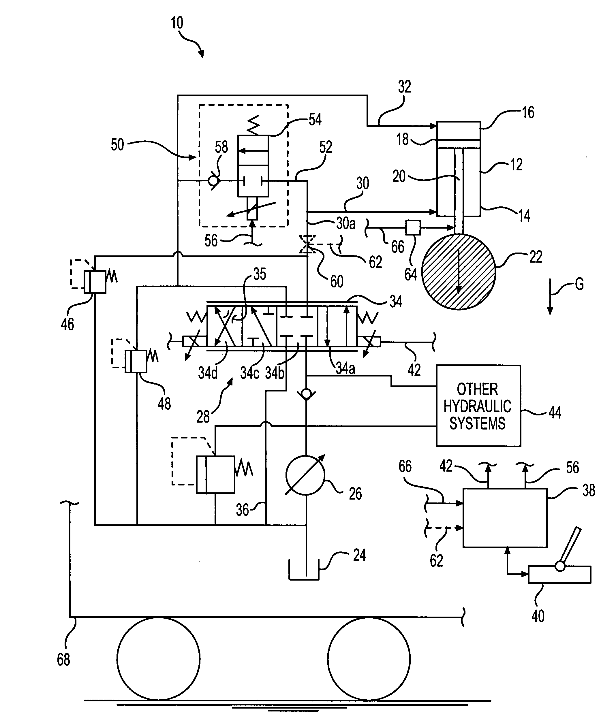
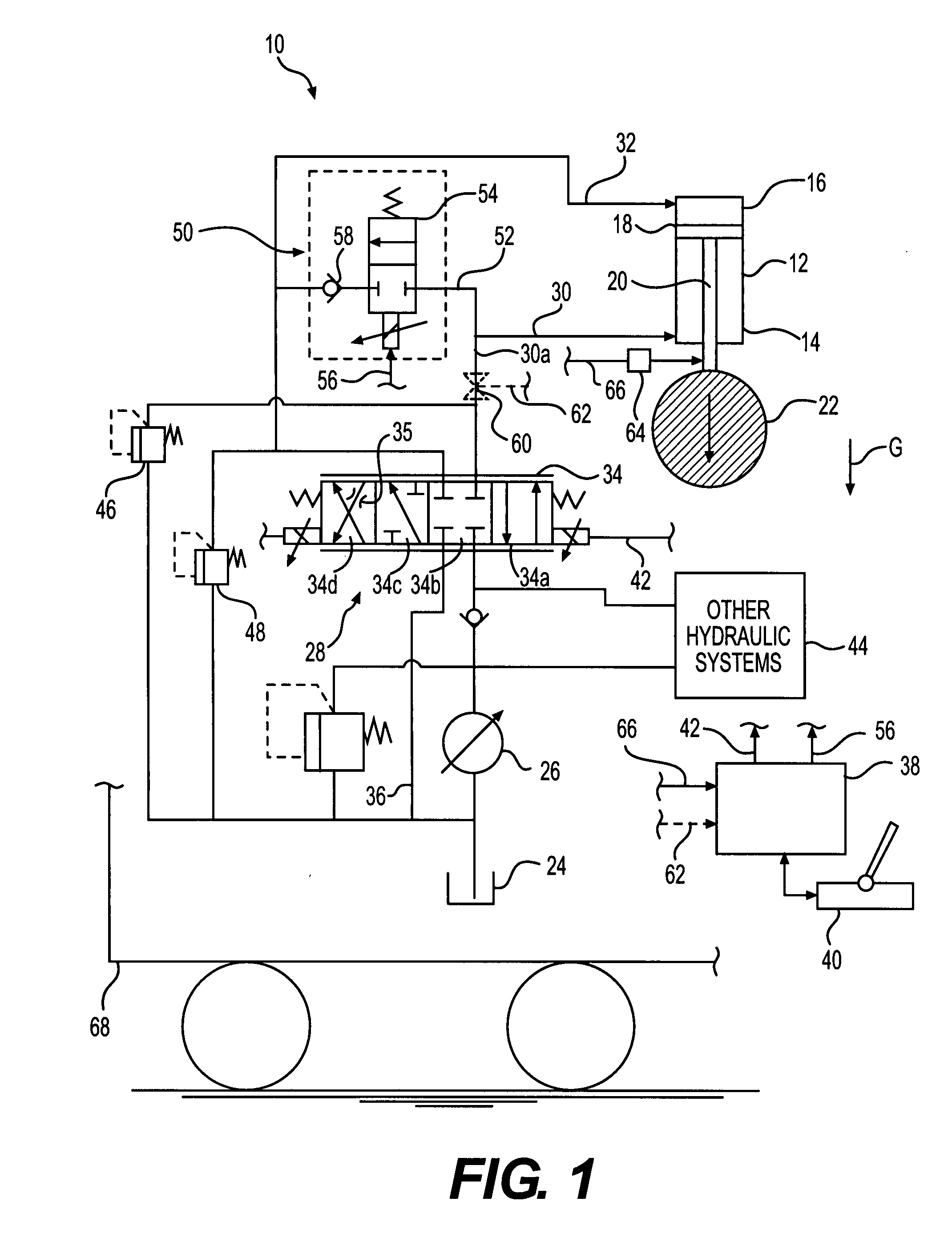
[0010]In one aspect of the disclosure, apparatus is disclosed for controlling a double-acting hydraulic cylinder during a load-induced rod-extending operation. The double-acting cylinder is of the type activated by fluid supplied from a reservoir by a pump, the cylinder having a rod end, a head end, and a piston connected to a rod for engaging the load. During the operation, the cylinder piston is urged toward the rod end by the load. With reference to FIG. 1, double-acting cylinder 12, as would be readily understood by one skilled in the art, includes rod end 14, head end 16, and piston 18 connected to rod 20 for engaging / supporting load 22. In some applications, such as the load-lowering operation in FIG. 1, cylinder 12 may be oriented with the rod extension direction in the direction of the force on the load tending to extend the rod, such as the force of gravity designated “G” in FIG. 1. However, the present disclosure also is intended to provide cylinder control in other load-i...


PUM


Abstract

Apparatus and methods are provided for controlling a double-acting hydraulic cylinder during a load-induced rod-extending operation, where the cylinder is activated by fluid supplied from a reservoir by a pump, and the cylinder has a rod end, a head end, a piston connected to a rod for engaging the load, the cylinder piston being urged toward the rod end by the load during the operation. The apparatus includes a cylinder activating circuit including an activation valve for providing a flow path from the pump to the cylinder head end; a flow regeneration circuit fluidly connecting the cylinder rod end and the cylinder head end and configured for providing flow from the cylinder rod end to the cylinder head end during rod extension, the regeneration circuit including a regeneration flow valve; and a controller operatively connected to the regeneration flow valve and the activation valve, the controller being responsive to rod-extending rate demands from an operator to control the activation valve to provide flow from the pump to the head end and to control the regeneration valve to provide flow from the rod end to the head end. The cylinder activating circuit also includes a return flow path and a return valve positioned in the return flow path and configured to control flow from the cylinder rod end to the fluid reservoir. Both the activation valve and the return valve are controllable by the controller independently from the regeneration flow valve.

Description

TECHNICAL FIELD[0001]This invention relates to the control of double-acting hydraulic cylinders e.g. in earth-moving equipment. In particular, this invention relates to use of flow regeneration to control double-acting cylinders in load-lowering and other operations where the cylinder rod extends under the influence of a load during the operation.BACKGROUND[0002]Use of flow regeneration circuits in controlling double-acting cylinders, including cylinders with a main directional control valve, is known. U.S. Pat. No. 6,267,041 (Skiba et al.) discloses a fluid regeneration circuit for a hydraulic cylinder having a directional control valve, wherein the regeneration flow path includes a separate regeneration valve between the rod end and head end. The regeneration valve is under the control of a controller and directs flow from the rod end to either the head end or to the system tank during certain rod extending operations. However, such systems cannot accommodate certain operations wh...

Claims


Application Information

Patent Timeline
Patent Type & Authority Applications(United States)
IPC IPC(8): F04B49/00B66F9/00F01C20/24
CPCE02F9/2203E02F9/2228E02F9/2296F15B11/024F15B2211/3122F15B2211/88F15B2211/61F15B2211/6346F15B2211/7053F15B2211/761F15B2211/3144
Inventor LIN, HONG-CHINSCHIMPF, JAMES EUGENEFERRIER, JAMES THOMAS
Owner CATERPILLAR INC
Why Eureka
Try Eureka