
Data Transfer Controlling Method, Content Transfer Controlling Method, Content Processing Information Acquisition Method And Content Transfer System

a technology of content transfer and control method, applied in the direction of program/content distribution protection, fault response, instruments, etc., can solve the problems of limited user's use of content, digital content can be easily exposed to illegal copying and use, and digital content cannot be used without a legal authentication process, so as to improve transmission efficiency

Inactive Publication Date: 2009-06-04
LG ELECTRONICS INC
View PDF99 Cites 67 Cited by
  • Summary
  • Abstract
  • Description
  • Claims
  • Application Information

AI Technical Summary

Benefits of technology

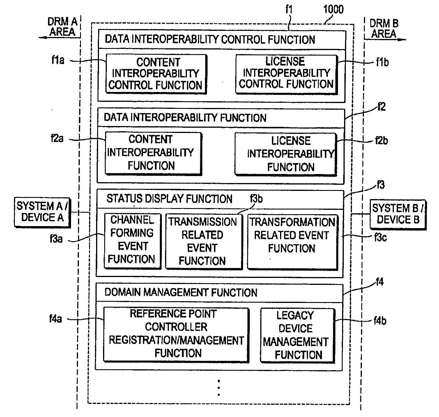
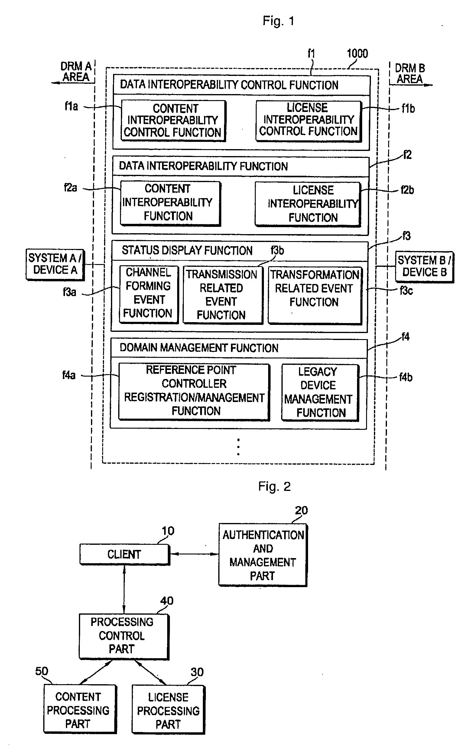
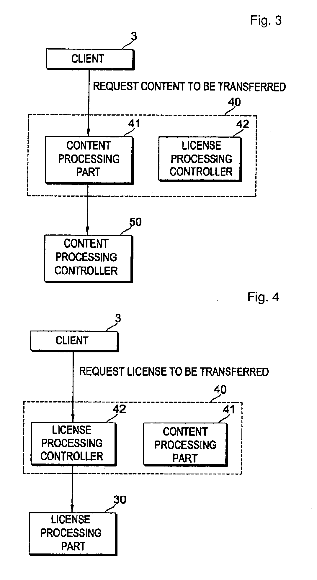
The present invention provides a method for controlling data transfer in a data interoperable environment, which allows for secure and efficient transmission of digital content in aDRM compatible environment. The method involves forming a chain of entities based on information gathered from the entities and transmitting a plurality of data through the chain. The method also allows for a secure authenticated channel for transmitting a plurality of contents in aDRM compatible environment. The technical effects of the invention include improved security and flexibility in distribution structures of digital content, as well as increased compatibility among different types ofDRMs.

Problems solved by technology

In general, unlike an analogue content, since a digital content can be unlimitedly copied without a loss of information, the digital content can be easily exposed to illegal copy and use.
Accordingly, although the digital content is casually obtained by a predetermined user, the digital content cannot be used without a legal authentication process.
This is due to technical and political closure properties of the DRM.
However, there is a problem that it is limited for a user to use the content.
The aforementioned problem deteriorates flexibility of a distribution structure of digital contents.
Finally, the problem causes limitation of digital content services.

Method used


Image

  • Data Transfer Controlling Method, Content Transfer Controlling Method, Content Processing Information Acquisition Method And Content Transfer System
  • Data Transfer Controlling Method, Content Transfer Controlling Method, Content Processing Information Acquisition Method And Content Transfer System
  • Data Transfer Controlling Method, Content Transfer Controlling Method, Content Processing Information Acquisition Method And Content Transfer System

Examples


example 1-1

[0136]First, a data format of a domain payload data unit (DPDU) is defined before the procedure of selecting a reference point controller is described. The DPDU is a normalized data format for transmitting device information of each device, when the reference point is selected.

[0137]FIG. 6 illustrates an example of a format of a DPDU data packet needed for selecting a reference point controller.

[0138]Referring to FIG. 6, the DPDU is constructed with a domain header and a domain payload.

[0139]The domain header includes a device capability identifier (hereinafter, abbreviated to DC-ID), a domain identifier (hereinafter, abbreviated to D-ID), and a device entity identifier (hereinafter, abbreviated to DE-ID).

[0140]The DC-ID is information used to identify a capability value of a device. At this time, the capability value may be information for displaying capability of a device with respect to a predetermined item, for example, a residual energy amount, a hardware specification, a netwo...

example 1.2

[0166]Hereinafter, Example 1-2 that is another example of a method of selecting a reference point controller will be described.

[0167]In the method of selecting a reference point controller of Example 1-2, the devices (for example, client devices), which desire to be registered with the domain, report the device information of the devices to the domain manager, and the domain manager selects the reference point controller based on the reported device information. At this time, the device information may include information on the domain, which the device subscribes to, information on the capability of the device, identification information of the device, and the like. For example, the device information may be a DPDU.

[0168]FIG. 8 is a flowchart illustrating a method of selecting a reference point controller according to Example 1-2.

[0169]Referring to FIG. 8, when the procedure starts, the devices to subscribe a domain set DC-ID values X, D-ID values Y, and DE-ID values Z to predeterm...

example 1-3

[0178]In a method of selecting a reference point controller according to Example 1-3, the reference point controller is selected based on setting information that is previously set by an administrator or user or is arbitrarily set. For example, when the administrator or user inputs the setting information into the domain manager, the domain manager can select the reference point controller based on the setting information. Alternatively, the administrator or user may directly select the device to be used as the reference point controller by the user and establish the reference point controller. Accordingly, in Example 1-3, the device desired by the administrator or user is selected, or any device is selected as the reference point controller.

[0179]The method of selecting the reference point controller, which is to determine a range of the local area, when the domain is initially constructed, has been described through Examples 1-1 to 1-3. When the reference point controller is selec...


PUM


Abstract

A method of controlling data transfer, a method of controlling content transfer, a method of obtaining content processing information, and a system for transferring content are provided. The method of controlling data transfer in a data interoperable environment includes: receiving a request for transmitting data from a client; gathering information on entities which are to participate in transmitting data; forming a chain including at least two entities by using the gathered information on the entities; transmitting a plurality of data through the chain; and receiving an event message for representing a transmission status of the data transmitted from at least one of the entities included in the chain. Accordingly, it is possible to control a transmission of the data so that the plurality of data can be transmitted through a single session and to receive the transmission status of the data as an event message.

Description

CROSS-REFERENCE TO RELATED APPLICATIONS[0001]This application is a continuation of U.S. application Ser. No. 12 / 281,633, filed Sep. 4, 2008, now pending, which is a 371 of International Application No.: PCT / KR2007 / 001110, filed Mar. 6, 2007, which claims priority from U.S. Provisional Application No. 60 / 778,928, filed Mar. 6, 2006, U.S. Provisional Application No. 60 / 743,417 filed Mar. 7, 2006, U.S. Provisional Application No. 60 / 744,322 filed Apr. 5, 2006, U.S. Provisional Application No. 60 / 744,811 filed Apr. 13, 2006, U.S. Provisional Application No. 60 / 799,411 filed May 9, 2006, U.S. Provisional Application No. 60 / 802,943 filed May 23, 2006, U.S. Provisional Application No. 60 / 803,834 filed Jun. 2, 2006, U.S. Provisional Application No. 60 / 814,977 filed Jun. 19, 2006, U.S. Provisional Application No. 60 / 832,514 filed Jul. 20, 2006, U.S. Provisional Application No. 60 / 824,700 filed Sep. 6, 2006, U.S. Provisional Application No. 60 / 862,684 filed Oct. 24, 2006, U.S. Provisional App...

Claims


Application Information

Patent Timeline
Patent Type & Authority Applications(United States)
IPC IPC(8): G06F11/16
CPCG06F21/10H04L63/0428G06F2221/0733G06F2221/0759H04L63/10G06F21/1063G06F21/1073
Inventor JEONG, MAN-SOOPARK, IL-GONPAK, KOO-YONGCHUNG, MIN-GYUCHO, SUNG-HYUNKIM, SOO-JUNGK, KIRAN KUMAR
Owner LG ELECTRONICS INC
Learn More