Inner rotor brushless motor

Inactive Publication Date: 2009-06-11
SHINANO KENSHI
View PDF4 Cites 7 Cited by
  • Summary
  • Abstract
  • Description
  • Claims
  • Application Information

AI Technical Summary

Benefits of technology

[0009]Also, in the case of electronic appliances used in vehicles, although the number of modular components and substrate-mounted electronic components such as sensors and motors is increasing due to comfort, safety, and environmental considerations, in response to environmental concerns, it is necessary to reduce the size and weight of the motors to reduce the overall weight of the vehicle.
[0021]By constructing a fan motor for use in a vehicle by attaching a fan to a shaft end of the motor shaft that extends out of the bracket, it is possible for the fan to draw air from the center in the axial direction and expel air toward the outer circumference. For this reason, it becomes easier for heat generated by heat generating components and the motor coils to dissipate via the bracket, and therefore the dissipation of heat can be further improved.

Problems solved by technology

However, for an outer rotor or inner rotor brushless motor, the thickness of the motor substrate on which the motor driving circuit is formed is added to the thickness of the stator core and / or the rotor, resulting in the problem of the motor construction tending to be thick in the axial direction.
In addition, although the number of electronic components mounted in vehicles is increasing, to reduce the space taken up by such components in a vehicle, there is demand for reductions in the thickness of (i.e., to flatten) motors in the axial direction without reducing the motor performance.

Method used


Image

  • Inner rotor brushless motor
  • Inner rotor brushless motor
  • Inner rotor brushless motor

Examples


Embodiment Construction

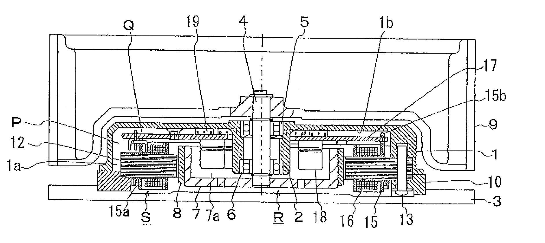
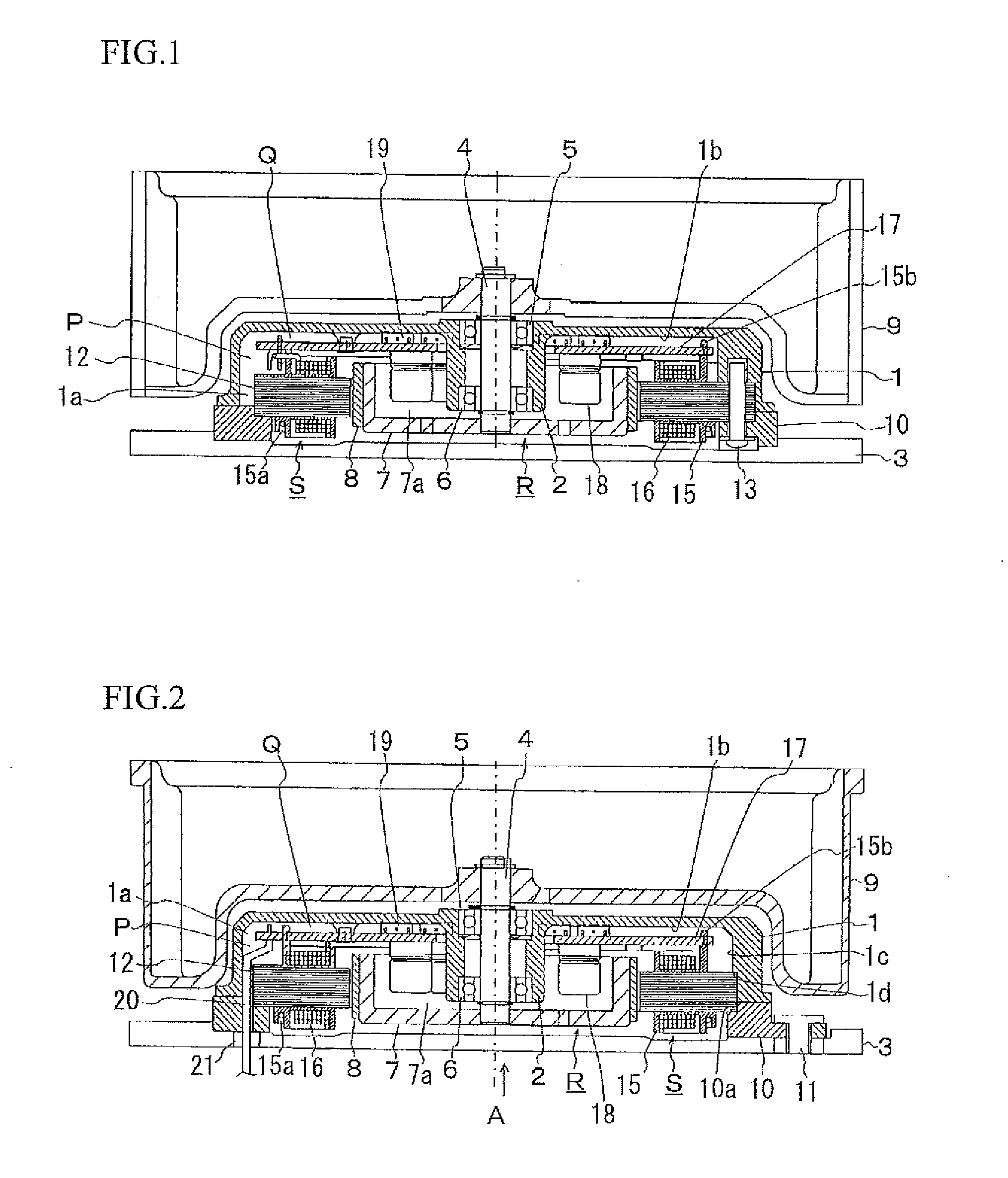
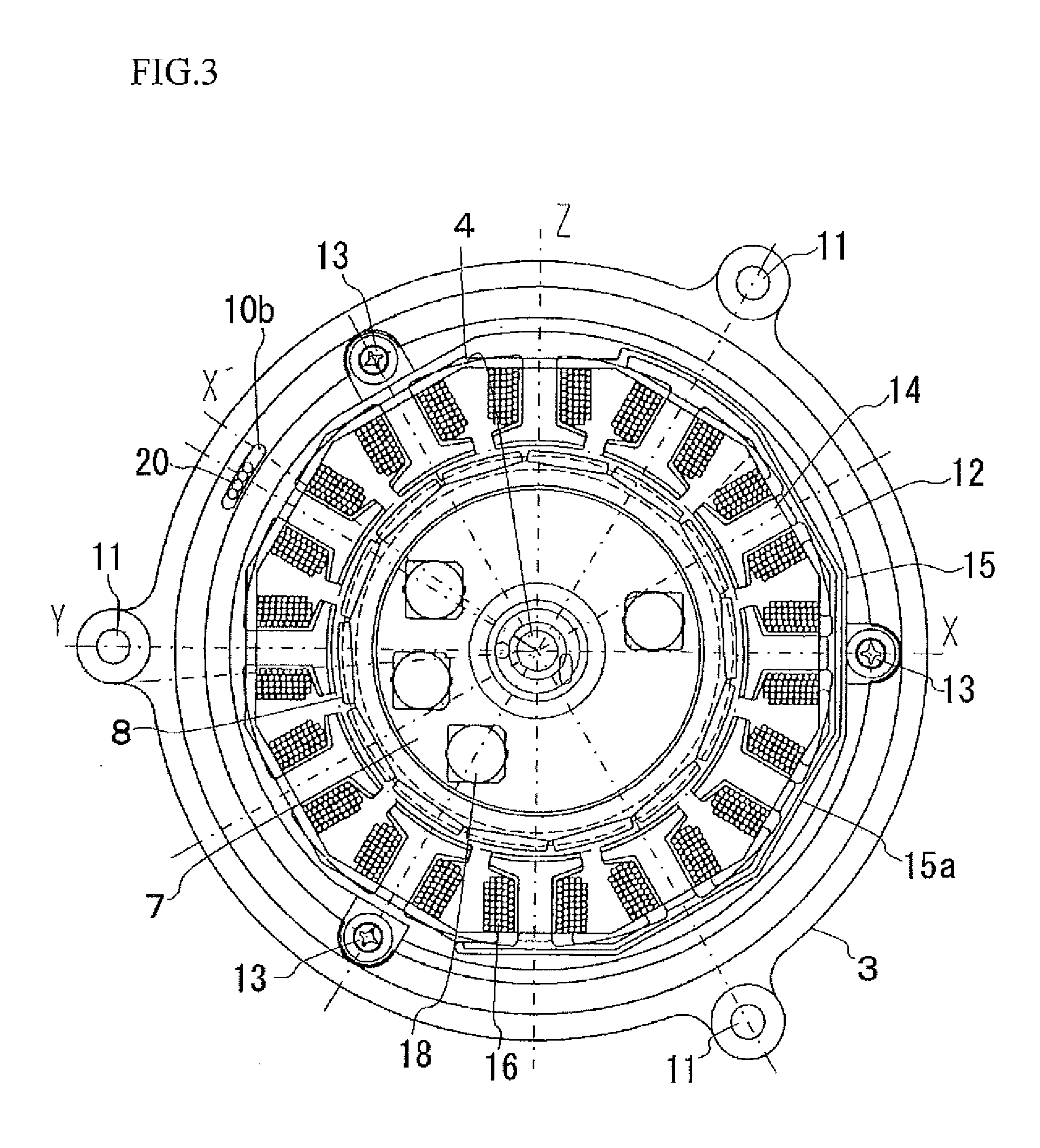
[0025]A preferred embodiment of an inner rotor brushless motor according to the present invention will now be described with reference to the attached drawings. The present embodiment is described by way of an example of a fan motor for use in a vehicle (an inner rotor DC brushless motor) where the rotor is disposed within a space surrounded by a ring-shaped stator core. FIG. 1 is a cross-sectional view along a line X-O-Z in FIG. 3, FIG. 2 is a cross-sectional view along a line Y-O-X′ in FIG. 3, and FIG. 3 is an internal plan view when looking from the direction of the arrow A in FIG. 2.

[0026]The overall construction of an inner rotor DC brushless motor will now be described with reference to FIGS. 1 to 3. In FIG. 1, a hollow cylinder portion 2 is erected in a center of a bracket opening 1 a of a cup-shaped bracket 1. In the hollow cylinder portion 2, a motor shaft 4 is rotatably supported via bearing portions (such as ball bearings or sleeve bearings) 5, 6. The bracket 1 serves as ...


PUM


Abstract

An inner rotor brushless motor is miniaturized, flattened and made lighter without reducing motor performance. A rotor and a stator are enclosed inside a sealed case (i.e., a sealed space) assembled by covering an attachment base with a cup-shaped bracket. A motor substrate on which a motor driving circuit is formed is provided in a gap formed in an axial direction between (i) the rotor and the stator and (ii) a base portion inside a bracket opening of the bracket.

Description

BACKGROUND OF THE INVENTION[0001]1. Field of the Invention[0002]The present invention relates to an inner rotor brushless motor that is used in a vehicle air conditioner, a battery cooling apparatus, or the like.[0003]2. Related Art[0004]As one example, an outer rotor DC brushless motor used as the driving apparatus for a fan used in a vehicle will now be described. A motor substrate on which a driving circuit is provided is split on two levels and enclosed inside an upper and lower housing that are made of resin. A concave is formed in the upper housing and a bearing sleeve is provided inside the concave so as to protrude vertically upward. A bearing shaft is rotatably supported in the bearing sleeve. The bearing shaft extends beyond the rotor and a fan is provided on the front end of the shaft. The stator core is assembled so as to be slidably fitted onto the bearing sleeve and contacts a stepped portion thereof.[0005]When the rotor is rotated, air is sucked in from air inlets pro...

Claims


Application Information

Patent Timeline
IPC IPC(8): H02K21/14
CPCH02K5/10H02K21/16H02K11/0073H02K9/14H02K11/33
Inventor YANO, TADASHIMARUYAMA, NOBUCHIKA
Owner SHINANO KENSHI
Why Eureka
Try Eureka