

Motor
- Summary
- Abstract
- Description
- Claims
- Application Information
AI Technical Summary
Benefits of technology
Problems solved by technology
Method used
Image

Examples
Embodiment Construction
of the present invention relate to a motor.
[0003]2. Description of the Related Art
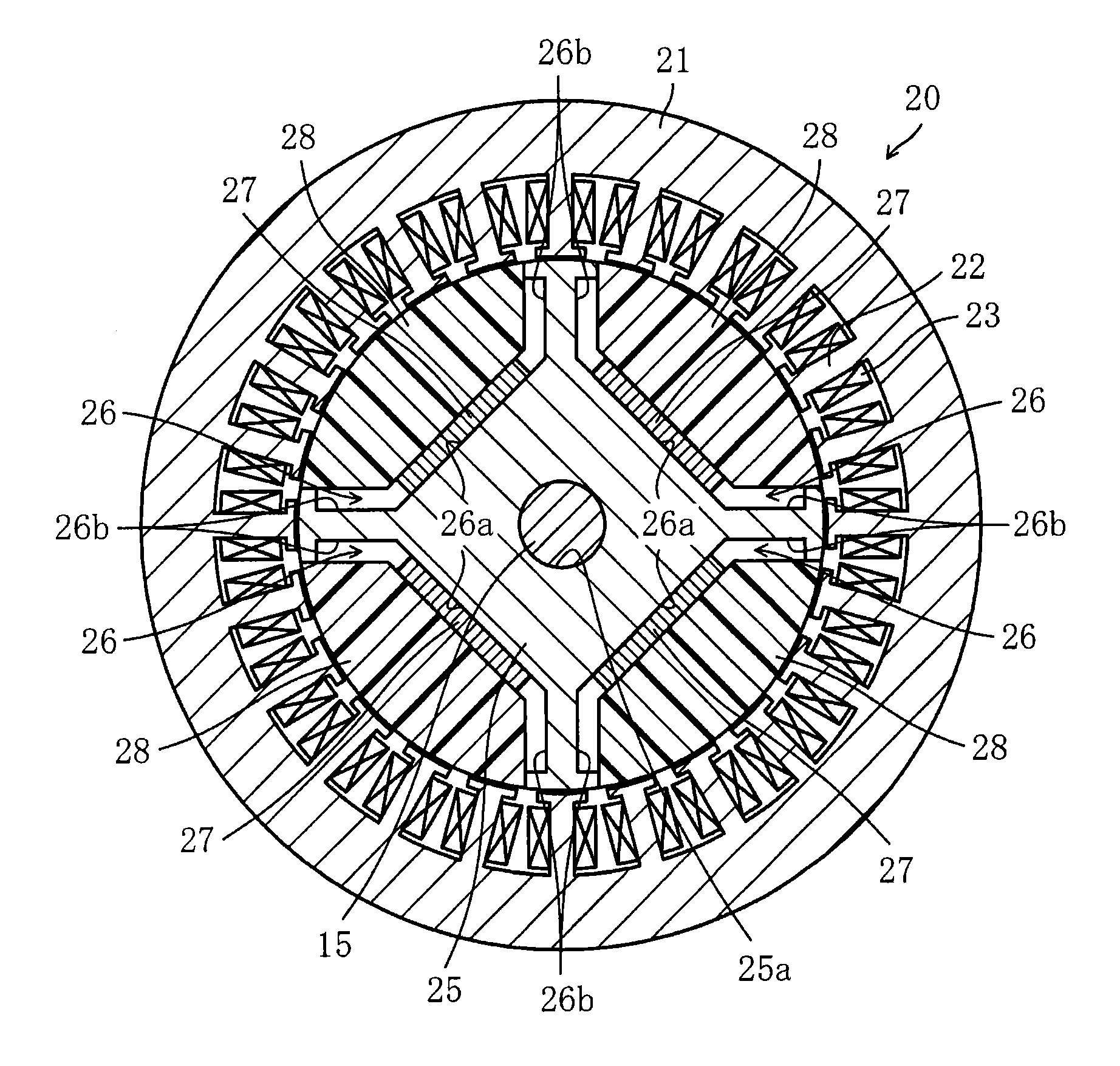
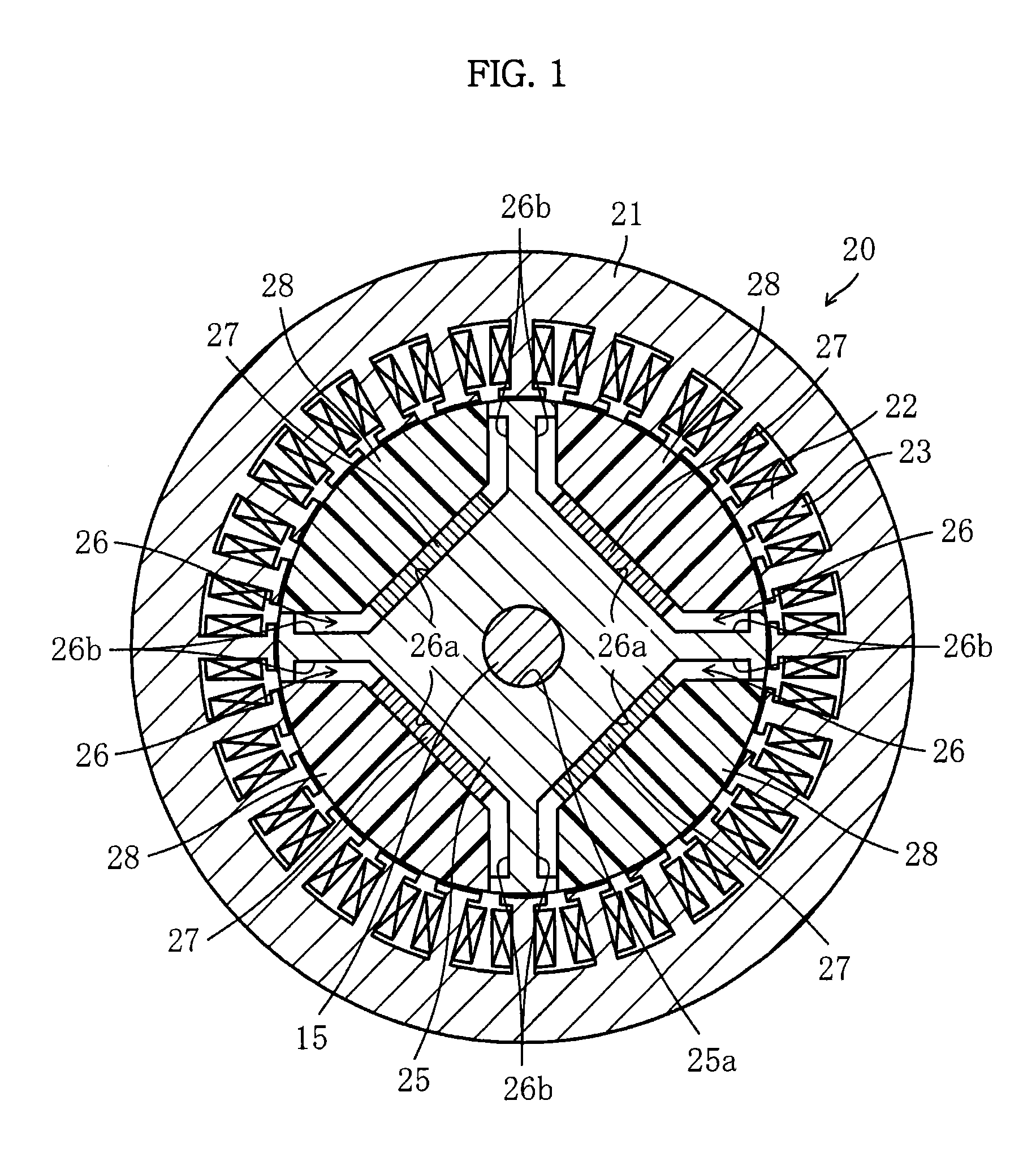
[0004]Japanese Patent Application Publication No. 2010-154755 discloses a motor including a ring-shaped stator having a plurality of coils and a rotor disposed inside the stator, the rotor having a permanent magnet embed therein, wherein the rotor is rotated by interaction between a rotating magnetic field generated by the coils and a magnetic field generated by the permanent magnet of the rotor.
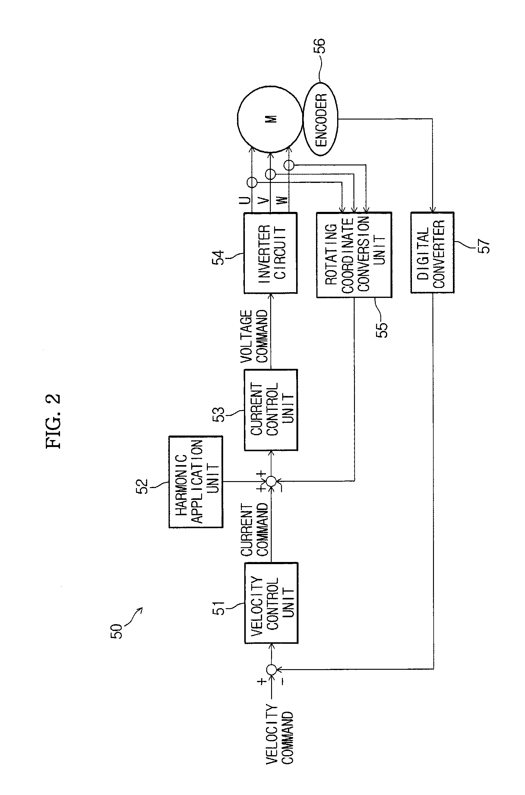
[0005]For a motor using a permanent magnet as a field magnet, field flux is uniform, and therefore, stray voltage is increased in proportion to rpm. Also, the maximum rpm at a predetermined torque area is decided based on a relationship between stray voltage and an output voltage of an inverter driving circuit. Specifically, current supplied to the motor is reduced due to limitations in output voltage of the inverter driving circuit with the result that torque is lowered, and the maximum rpm is kept low.
[0006]I...
PUM
 Abstract
Description
Claims
Application Information