Transformer inrush current detector

a transformer and detector technology, applied in the direction of emergency protective circuit arrangement, electrical equipment, emergency protective arrangement details, etc., can solve the problems of transformer windings temporarily spiking to extremely high levels, losing inductive characteristics, and within the protection zone, etc., to achieve excellent response, low inductance, and high linearity

Active Publication Date: 2009-06-11
EATON INTELLIGENT POWER LIMITED
View PDF16 Cites 41 Cited by
  • Summary
  • Abstract
  • Description
  • Claims
  • Application Information

AI Technical Summary

Benefits of technology

[0011]Rogowski coils can provide low inductance and excellent response to fast-changing currents since they have air cores rather than an iron core. Without an iron core to saturate, a Rogowski coil can be highly linear even in high current applications. Furthermore, having reduced saturation concerns, the Rogowski coil protection system may employ a single slope response with increased sensitivity. Also, the geometry of a Rogowski coil may provide a current sensor that is significantly immune to electromagnetic interference.
[0012]The present invention further relates to methods for detecting inrush current for a power transformer. Using the output of the Rogowski coils, which is proportional to the derivative of the sensed current, periodic low di / dt periods in the sensed current are used to detect power transformer inrush conditions. Another aspect of the present invention relates to discrete time sampling techniques for identifying the low di / dt portions within the sensed current. Effective detection of power transformer inrush conditions can enable blocking of the protection system during inrush where the differential current may exceed the differential threshold without the presence of an actual fault.

Problems solved by technology

If the difference exceeds the relay setting (differential threshold), a fault within the protection zone is likely, and a protection relay initiates operation of a circuit breaker or other device to isolate the power transformer.
A differential protection system with a lower differential threshold may be more sensitive, but can be falsely triggered by non fault events.
When a transformer core saturates, it may lose its inductive characteristics allowing currents in the transformer windings to temporarily spike to extremely high levels.
Since inrush current generally flows on only one side of the transformer, the current differential between the primary and secondary sides of the transformer easily can exceed the differential threshold of the differential protection system and can cause the protection relay to isolate the power transformer even though an actual fault does not exist.
Varying response characteristics at this second harmonic for different transformers, as well as the complexity of the related filter designs, often complicate such traditional approaches.

Method used


Image

  • Transformer inrush current detector
  • Transformer inrush current detector
  • Transformer inrush current detector

Examples


Embodiment Construction

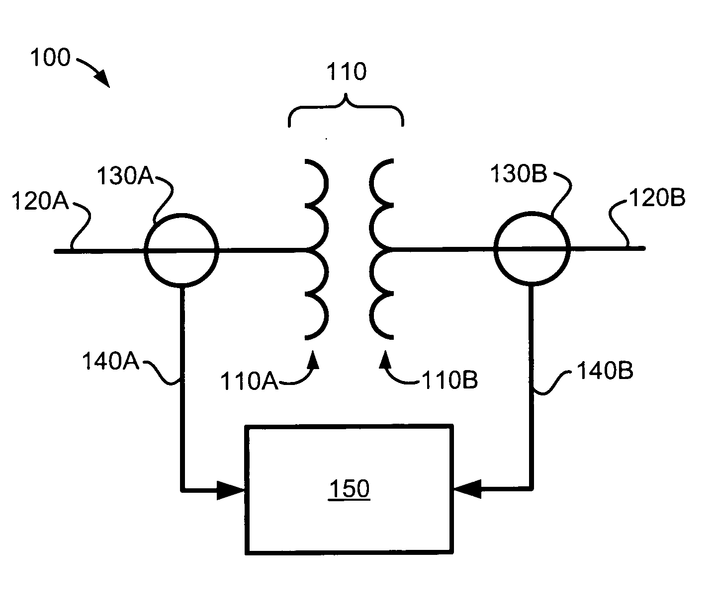
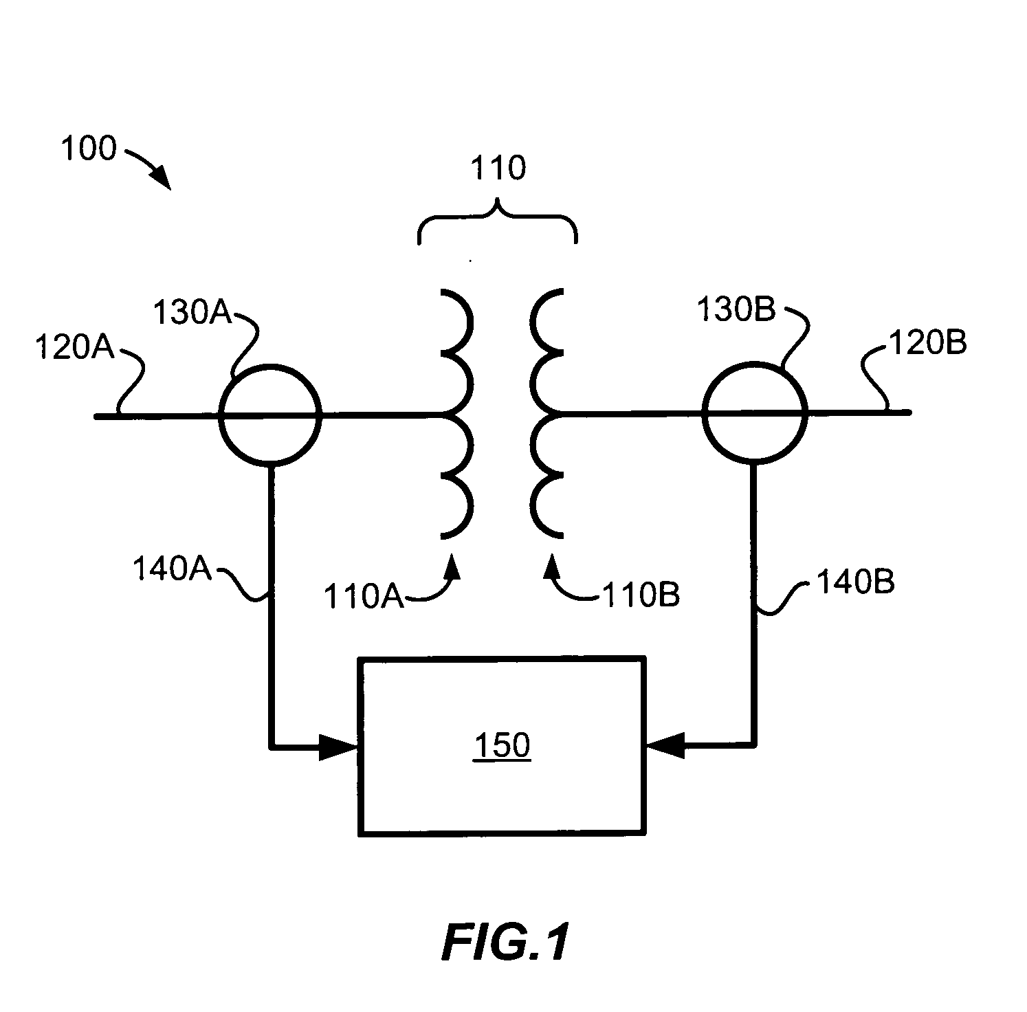
[0020]The present invention relates to a differential protection system for power transformers using Rogowski coils as current sensors and to methods for detecting inrush current for a power transformer. Using the output of the Rogowski coils, which is proportional to the derivative of the sensed current, periodic low di / dt periods in the sensed current are used to detect power transformer inrush conditions. Discrete time sampling techniques can be used for identifying the low di / dt portions within the sensed current. Effective detection of power transformer inrush conditions can enable blocking of the protection system during inrush where the differential current may exceed the differential threshold without the presence of an actual fault.

[0021]The invention can be embodied in many different forms and should not be construed as limited to the embodiments set forth herein; rather, these embodiments are provided so that this disclosure will be thorough and complete, and will fully c...


PUM


Abstract

A differential protection system for power transformers using Rogowski coils as current sensors can support an inrush current detection method based on sensing lows in the derivative of the sensed current. Effective detection of power transformer inrush conditions can enable blocking of a protection relay during inrush where the differential current may exceed a differential threshold value indicative of a fault without the presence of an actual fault. The outputs of the Rogowski coils, being proportional to the first time derivative of the sensed current, may be useful in the inrush detection method. Also, with reduced saturation concerns, the Rogowski coil protection system may employ a single slope response with increased sensitivity. A discrete time sampling technique for identifying low di/dt portions within the sensed current also may be useful in detecting power transformer inrush conditions.

Description

FIELD OF THE INVENTION[0001]The present invention relates to a differential protection system for power transformers and more specifically to a power transformer protection system using Rogowski coils for current sensing and for detecting inrush current of the power transformer.BACKGROUND[0002]A power transformer is used to step up, or step down, a voltage. That is, the output voltage is the input voltage times a step factor. The step factor is generally called the transformer ratio and is also known as turns ratio. This ratio is defined as the ratio of the primary and secondary voltages for a two winding transformer. Generally, a transformer that steps up voltage will step down current while a transformer that steps down voltage will step up current. Since power equals voltage times current, power is the same on both sides of the transformer, ignoring transformer losses. Aside from being multiplied by the transformer ratio, the current entering a power transformer should be equal t...

Claims


Application Information

Patent Timeline
Patent Type & Authority Applications(United States)
IPC IPC(8): H02H7/04
CPCH02H3/44H02H1/043H02H7/0455H02H3/28
Inventor KOJOVIC, LJUBOMIR A.BISHOP, MARTIN T.DAY, TIMOTHY R.
Owner EATON INTELLIGENT POWER LIMITED
Why Eureka
Try Eureka