Diagnostic imaging apparatus, magnetic resonance imaging apparatus, and x-ray ct apparatus

a diagnostic imaging and magnetic resonance imaging technology, applied in the field of diagnostic imaging apparatus, magnetic resonance imaging apparatus, x-ray computed tomography (ct) apparatus, can solve the problems of increased burden on the operator and patient, unstable image quality,

Active Publication Date: 2009-06-11
TOSHIBA MEDICAL SYST CORP
View PDF18 Cites 11 Cited by
  • Summary
  • Abstract
  • Description
  • Claims
  • Application Information

AI Technical Summary

Problems solved by technology

For this reason, according to the conventional methods, an examination time may be sometimes extended, so that burdens to an operator

Method used


Image

  • Diagnostic imaging apparatus, magnetic resonance imaging apparatus, and x-ray ct apparatus
  • Diagnostic imaging apparatus, magnetic resonance imaging apparatus, and x-ray ct apparatus
  • Diagnostic imaging apparatus, magnetic resonance imaging apparatus, and x-ray ct apparatus

Examples


first embodiment

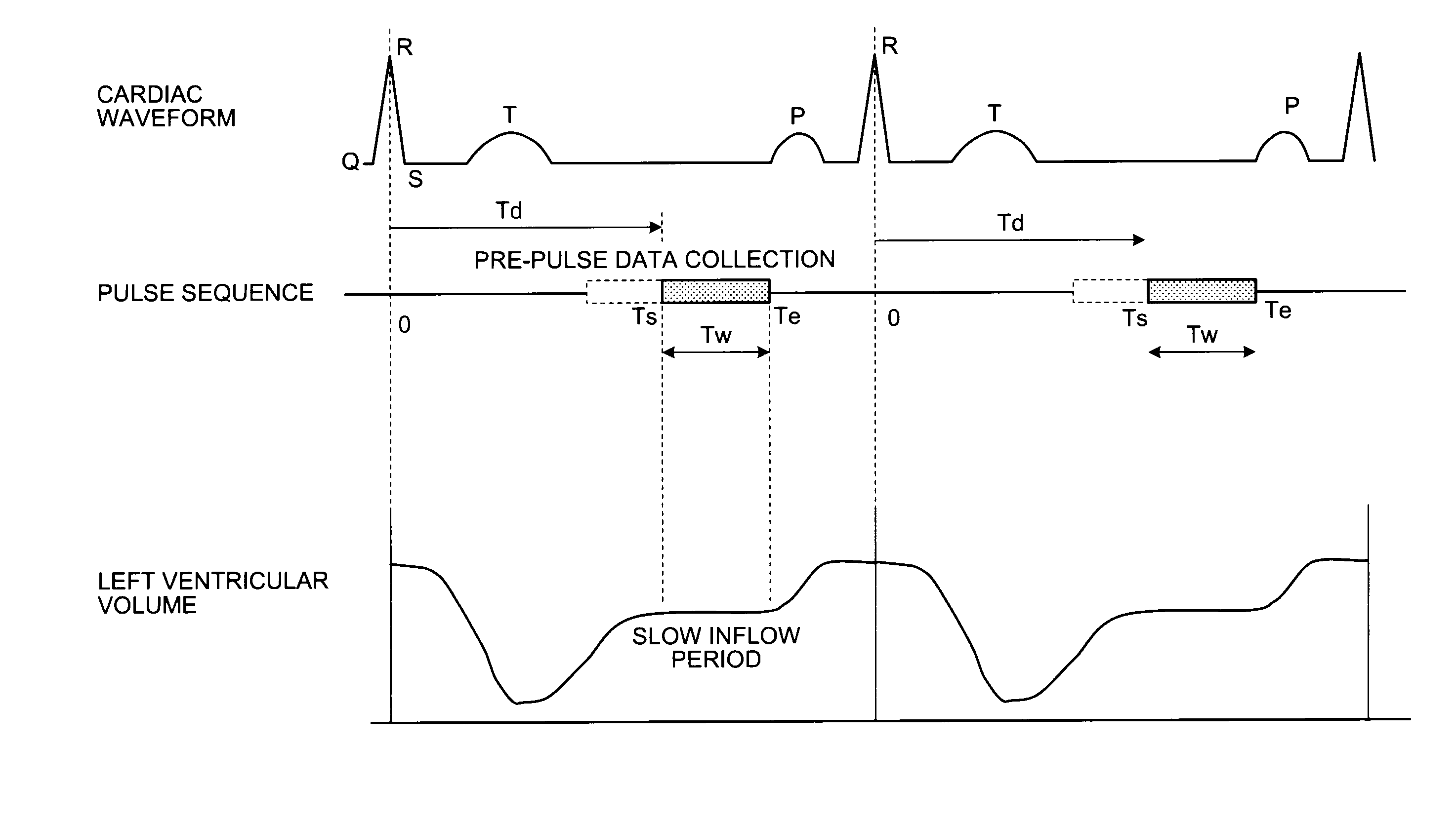
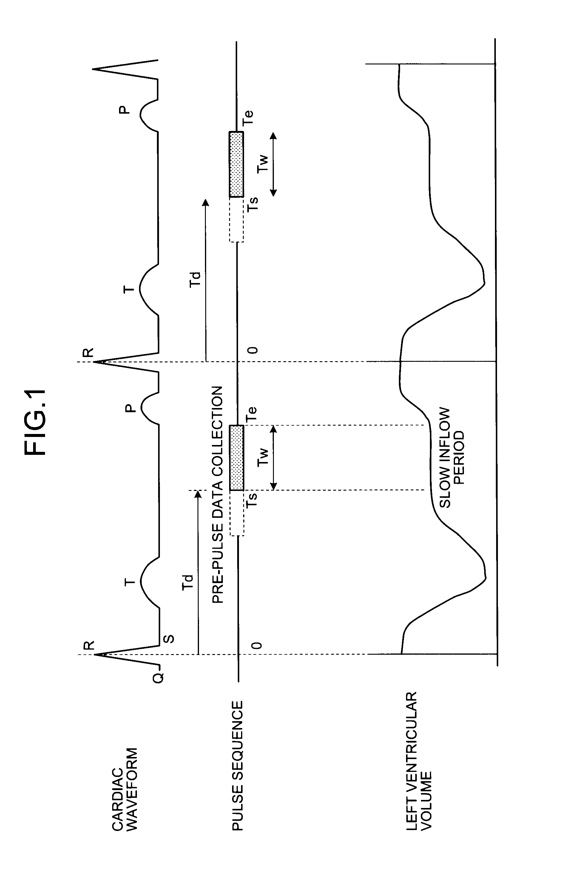
[0022]Prior to explanations of an MRI apparatus according to the present invention, a method of data collection and a flow of a conventional cardiac Magnetic Resonance (MR) examination performed by a conventional MRI apparatus are explained below.

[0023]First of all, a data collection method performed by the conventional MRI apparatus is explained below. FIG. 1 is a schematic diagram for explaining a data collection method performed by the conventional MRI apparatus. FIG. 1 depicts an example of a scanning method performed by an MRI apparatus for collecting data in a specific cardiac time phase in a cardiac cycle represented by coronary angiography as described in Stuber M, et al. “Submillimeter Three-dimensional Coronary MR Angiography with Real-Time Navigator Correction: Comparison of Navigator Locations”, Radiology 1999; 212: 579-587).

[0024]As shown with a cardiac waveform and a pulse sequence in FIG. 1, for example, the conventional MRI apparatus detects an R wave from the cardia...

second embodiment

[0083]FIG. 10 is a schematic diagram illustrating a configuration of an X-ray CT apparatus 200 according to the As shown in FIG. 10, the X-ray CT apparatus 200 includes a gantry apparatus 210, a patient couch 220, and a console device 230.

[0084]The gantry apparatus 210 collects projection data by irradiating the subject P with X-rays. The gantry apparatus 210 includes a high-voltage generating unit 211, an X-ray tube 212, an X-ray detector 213, a data collecting unit 214, a rotating frame 215, and a gantry driving unit 216.

[0085]The high-voltage generating unit 211 supplies a high voltage to the X-ray tube 212. The X-ray tube 212 generates X-rays with a high voltage supplied by the high-voltage generating unit 211. The X-ray detector 213 detects X-rays that have passed through the subject P. The data collecting unit 214 creates projection data by using the X-rays detected by the X-ray detector 213.

[0086]The rotating frame 215 is formed in a toroidal shape, and rotates rapidly and c...


PUM


Abstract

A diagnostic imaging apparatus includes a ventricular volume-variation measuring unit that measures sequential variations in a size of a ventricle within at least one heart beat, from images of a heart scanned in each of a plurality of time phases; a scanning-condition setting unit that specifies a time phase of little cardiac motion based on variations in the size of the ventricle measured by the ventricular volume-variation measuring unit, and sets scanning conditions so as to collect data in the specified time phase; and an imaging unit that collects data based on the scanning conditions set by the scanning-condition setting unit, and reconstructs an image from the collected data.

Description

CROSS-REFERENCE TO RELATED APPLICATIONS[0001]This application is based upon and claims the benefit of priority from the prior Japanese Patent Application No. 2007-317613, filed on Dec. 7, 2007, and No. 2008-272448, filed on Oct. 22, 2008; the entire contents of which are incorporated herein by reference.BACKGROUND OF THE INVENTION[0002]1. Field of the Invention[0003]The present invention relates to a diagnostic imaging apparatus, a magnetic resonance imaging apparatus, and an X-ray Computed Tomography (CT) apparatus each of which performs a scan by setting scanning conditions so as to collect data synchronously with a cardiac waveform of a subject. The present invention particularly relates to a technology for determining timing of little cardiac motion automatically without additional special scan or operator's determination.[0004]2. Description of the Related Art[0005]Conventionally, among methods of a cardiac scan performed by a magnetic resonance imaging apparatus, particularly ...

Claims


Application Information

Patent Timeline
IPC IPC(8): A61B5/055A61B6/00
CPCA61B5/024A61B5/055A61B6/503A61B6/504G01R33/5676G01R33/546G01R33/56325G01R33/5635G01R33/56366G01R33/543A61B5/0037
Inventor SUGIURA, SATOSHI
Owner TOSHIBA MEDICAL SYST CORP
Why Eureka
Try Eureka