
Cardiac impulse assist system

An auxiliary system and heart beating technology, applied in the direction of suction equipment, etc., can solve the problems of life being difficult to maintain, insurmountable, unable to work synchronously with heart beating, etc., to achieve the effect of correcting arrhythmia and small size

Inactive Publication Date: 2013-01-16
杨碧波
View PDF6 Cites 8 Cited by
  • Summary
  • Abstract
  • Description
  • Claims
  • Application Information

AI Technical Summary

Problems solved by technology

Once the heart function deteriorates, the self-beating ability decreases so that the ventricular contractility cannot overcome the aortic pressure formed by the axial flow pump auxiliary system, the ventricle stops bleeding, and the arterial blood pressure is completely expressed as non-pulsating pressure, and life is difficult to maintain
In addition, when the axial flow pump system runs at high speed and high flow rate, it is more destructive to the formed components of blood, which is not suitable for physiological needs, and it is difficult to maintain long-term use
[0009] None of the currently used cardiac assist devices have the ability to effectively work synchronously with the heartbeat; they do not have the ability to fully simulate the physiological pressure sequence in the ventricular chamber to assist the heart; they do not have the ability to be implanted into the ventricle to assist in repairing the shape of the heart and repairing the perforation of the interventricular septum; Not capable of correcting arrhythmias

Method used


Image

  • Cardiac impulse assist system
  • Cardiac impulse assist system
  • Cardiac impulse assist system

Examples


Embodiment Construction

[0032] The embodiments of the present invention will be described in detail below. The embodiments described below with reference to the drawings are intended to explain the present invention, but cannot be construed as a limitation to the present invention.

[0033] The first embodiment:

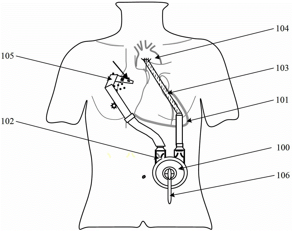
[0034] See Figure 8 , The heart beat assist system of the present invention includes:

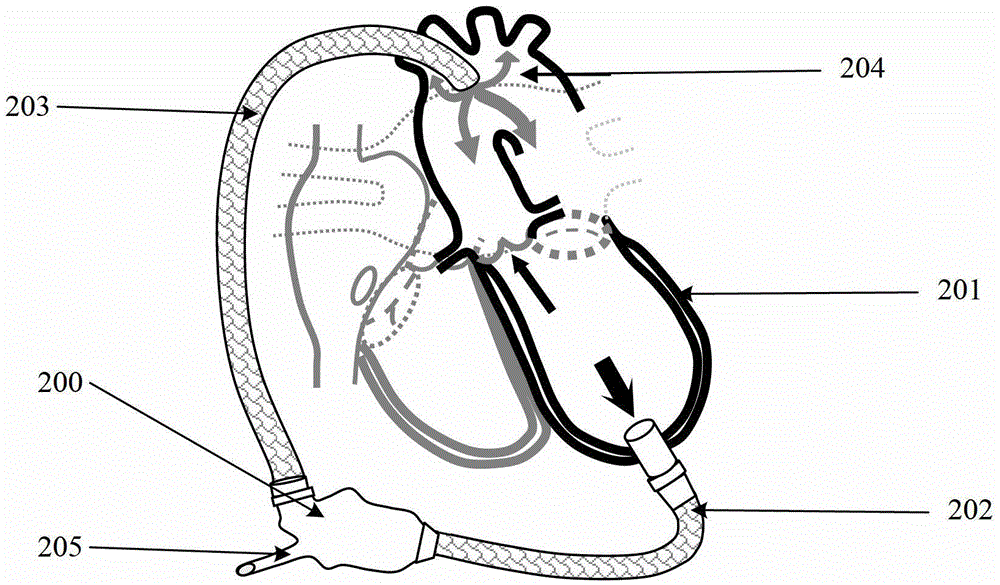
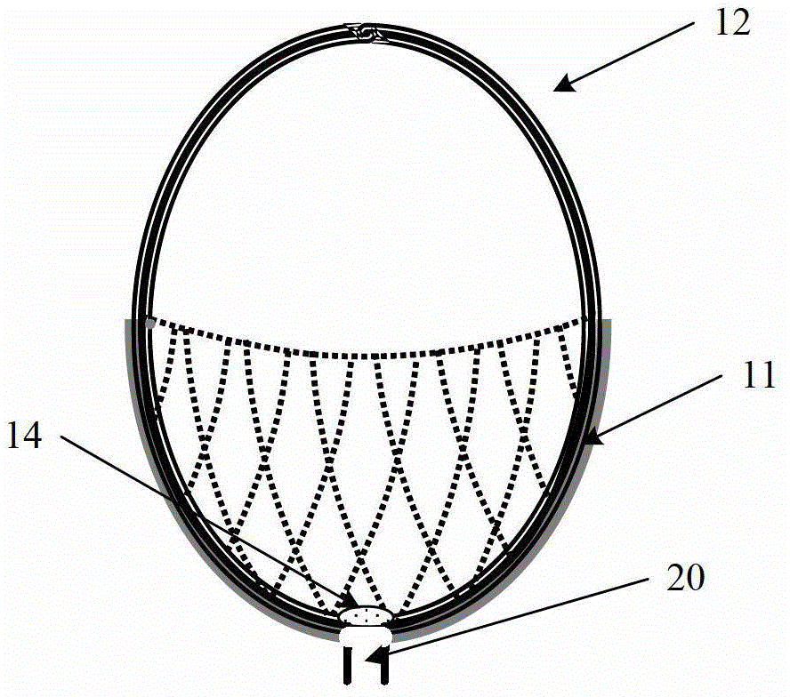
[0035] A ventricular volume adjusting device 10, which is implanted as a whole in the ventricle of a patient suffering from heart failure, for adjusting the ventricular volume;

[0036] Synchronization device 27, the sensor of the synchronization device 27 is connected to the heart for collecting ventricular contraction signals; the synchronization device 27 is equipped with an automatic defibrillation device and a synchronized treatment device, and the output terminals of the automatic defibrillation device and the synchronized treatment device are connected to heart;

[0037] The control device 26 is used for ...


PUM


Abstract

The invention discloses a cardiac impulse assist system, which comprises a ventricular volume regulating device, a synchronizer and a control device, wherein the ventricular volume regulating device is used for regulating ventricular volumes; a sensor of the synchronizer is connected to the heart; the synchronizer is used for collecting ventricular systole signals; and the control device is used for receiving the ventricular systole signals collected by the synchronizer, and is used for controlling the ventricular volume regulating device to synchronously reduce the ventricular volumes when ventricular systole is performed. An automatic defibrillating device and a synchronous treatment device are arranged in the synchronizer; a defibrillating electrode of the automatic defibrillating device is connected to the heart; a pacing electrode of the synchronous treatment device is implanted into a chamber of the heart. As the ventricular volume regulating device is small in size, the cardiac impulse assist system disclosed by the invention can be implanted into the chamber of the heart. The cardiac impulse assist system disclosed by the invention can be used for completely imitating a ventricular pressure-volume change rule, can work synchronously with cardiac impulse, and can be used for assist the heart to pulsate and do work so as to treat cardiac failure, promote ventricular restoration and repair the perforation of ventricular septum.

Description

[0001] This application is a divisional application for an invention patent application named: Heart Beat Assist System, application number: 200910177974.6, and application date: October 23, 2009. Technical field [0002] The invention relates to a medical device, in particular to a heart beat assist system. Background technique [0003] Heart failure is a syndrome caused by heart failure caused by various heart diseases. The reason is that the decrease of myocardial contractility causes the stroke volume to not meet the needs of the body's metabolism. At the same time, blood pooling in the heart increases the pressure in the heart cavity during diastole and enlarges the heart chamber, further reducing myocardial contractility and aggravating cardiac insufficiency. It causes obstruction of blood return in systemic and pulmonary circulation, congestion of body and pulmonary circulation, causing circulatory dysfunction and metabolic disorders of the body. When heart failure occurs,...

Claims


Application Information

Patent Timeline
IPC IPC(8): A61M1/12
Inventor 杨碧波
Owner 杨碧波
Learn More