Partial cascade thrust reverser

a thrust reverser and cascade technology, applied in the field of thrust reversers, can solve the problems of difficult reducing the size placing a heavy burden on the brakes and tires of the plane, etc., and achieve the effect of reducing the size and weight of the thrust reverser

Active Publication Date: 2009-06-18
SPIRIT AEROSYSTEMS
View PDF42 Cites 80 Cited by
  • Summary
  • Abstract
  • Description
  • Claims
  • Application Information

AI Technical Summary

Benefits of technology

[0007]The present teachings provide an improved thrust reverser that represents a distinct advance in the state of the art. Particularly, embodiments of the present technology provide a thrust reverser that includes a reduced-profile cascade element that reduces the size and weight of the thrust reverser.

Problems solved by technology

Airplanes powered by jet engines have high landing speeds, which can place a heavy burden on the planes' wheel brakes and tires during landing runs.
Unfortunately, reducing the size of the thrust reverser is challenging because the thrust reverser needs to be sufficiently large and durable to handle the fluid stream of the jet engine.

Method used


Image

  • Partial cascade thrust reverser
  • Partial cascade thrust reverser
  • Partial cascade thrust reverser

Examples


Embodiment Construction

[0017]The following detailed description of the present technology references the accompanying drawings that illustrated specific embodiments in which the technology can be practiced. The embodiments are intended to describe aspects of the technology in sufficient detail to enable those skilled in the art to practice the technology. Other embodiments can be utilized and changes can be made without departing from the scope of the present teachings. The following detailed description is, therefore, not to be taken in a limiting sense. The scope of the present invention is defined only by the appended claims, along with the full scope of equivalents to which such claims are entitled.

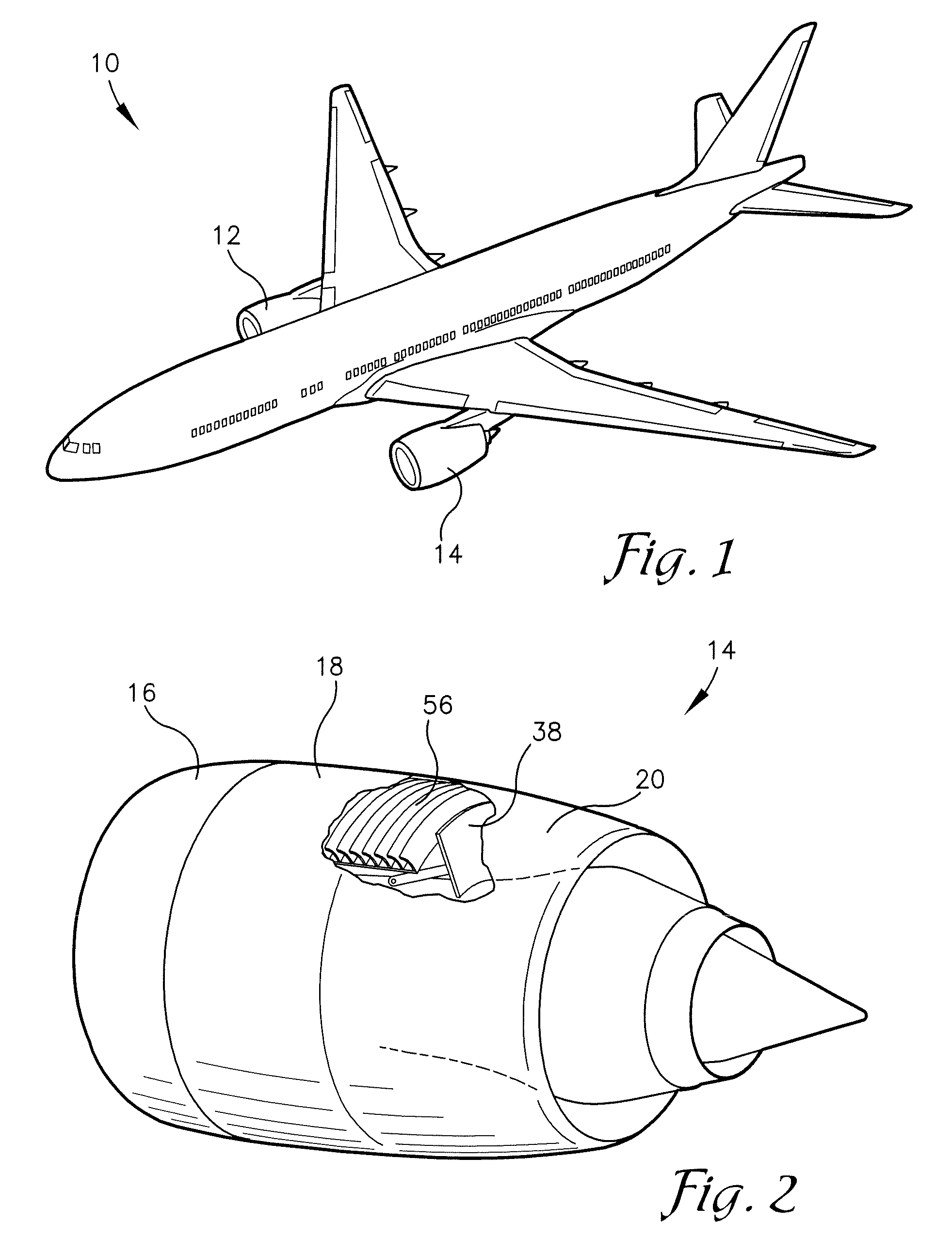
[0018]An aircraft 10 having a plurality of jet engines 12,14 incorporating principles of the present technology is illustrated in FIG. 1. The aircraft 10 may be a relatively large aircraft intended for commercial or military use, or may be a relatively small aircraft intended for private or corporate use. T...


PUM


Abstract

A thrust reverser for a jet engine comprises a translating wall section moveable between a stowed position and a deployed position. The translating wall section is adjacent an annular fan duct wall or other fixed portion of the jet engine when in the stowed position and is separated from the annular fan duct wall when in the deployed position, thereby creating an aperture through which a fluid stream passes. A fluid flow reverser element directs the fluid stream in a direction generally forward relative to the jet engine when the translating wall section is in the deployed position. The fluid flow reverser element extends only partially into the fluid stream such that only a first portion of fluid of the fluid stream engages the fluid flow reverser element. A second portion of the fluid stream is entrained in the first portion and is thereby directed forward relative to the jet engine.

Description

BACKGROUND[0001]1. Field[0002]The present technology relates to thrust reversers for jet engines. More particularly, embodiments of the technology involve a thrust reverser with a reduced-profile cascade element.[0003]2. Related Art[0004]Airplanes powered by jet engines have high landing speeds, which can place a heavy burden on the planes' wheel brakes and tires during landing runs. To reduce this burden, most jet-driven airplanes are provided with means to reverse the direction of flow of the jet stream during landing runs to produce a reverse thrust, thus slowing the airplane with the jet engines as opposed to the wheel brakes.[0005]Many different types of thrust reversers have been developed for this purpose, all based on the principle of blocking rearward flow of the jet stream and diverting the jet stream flow laterally, forwardly, or both. One type of thrust reverser, called the cascade type, uses a cascade element comprising an array of stacked or “cascading” arcuate vanes t...

Claims


Application Information

Patent Timeline
Patent Type & Authority Applications(United States)
IPC IPC(8): F02K1/12
CPCY02T50/671F02K1/72Y02T50/60
Inventor STERNBERGER, JOE E.
Owner SPIRIT AEROSYSTEMS
Why Eureka
Try Eureka