Cooling apparatus

a cooling apparatus and cooling technology, applied in lighting and heating apparatus, semiconductor devices, semiconductor/solid-state device details, etc., can solve the problems of insufficient cooling efficiency, large heat generation of electronic components, and insufficient quantity of heat pipes on the base, so as to improve the cooling efficiency of the cooling apparatus and increase the heat conducting area

Inactive Publication Date: 2009-06-18
COOLER MASTER CO LTD
View PDF0 Cites 11 Cited by
  • Summary
  • Abstract
  • Description
  • Claims
  • Application Information

AI Technical Summary

Benefits of technology

[0007]One particular aspect of the present invention is to provide a cooling apparatus of which the heat conducting area is increased with respect to its base area so that the cooling efficiency of the cooling apparatus is enhanced.
[0010]The present invention has the following characteristics. Because the heat pipes of the cooling apparatus are stacked, the quantity of the heat pipes is not limited by the dimension of the base and can be increased. Furthermore, a plurality of heat conducting columns is installed between the heat pipes so that the heat conducting area is increased. Thereby, the heat generated from the electronic components can be rapidly delivered to the cooler.

Problems solved by technology

When electric machines or electronic devices are operating, the electronic components often generate a substantial amount of heat.
However, because the dimension of the base of the cooling apparatus is small, the quantity of the heat pipes that can be disposed on the base is few.
The cooling efficiency is inadequate when the operation speed of the electronic components increases.

Method used


Image

  • Cooling apparatus
  • Cooling apparatus
  • Cooling apparatus

Examples


Embodiment Construction

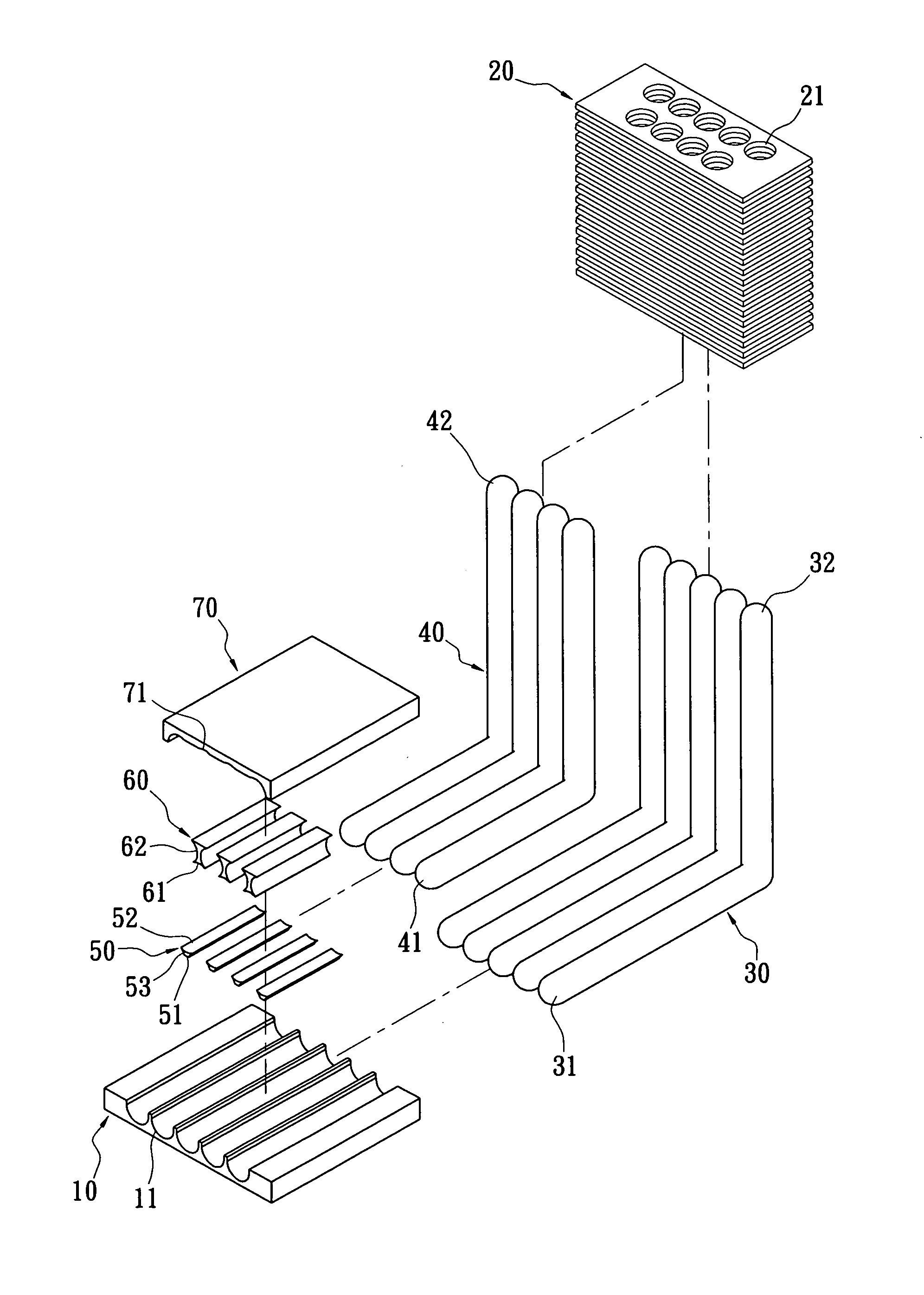
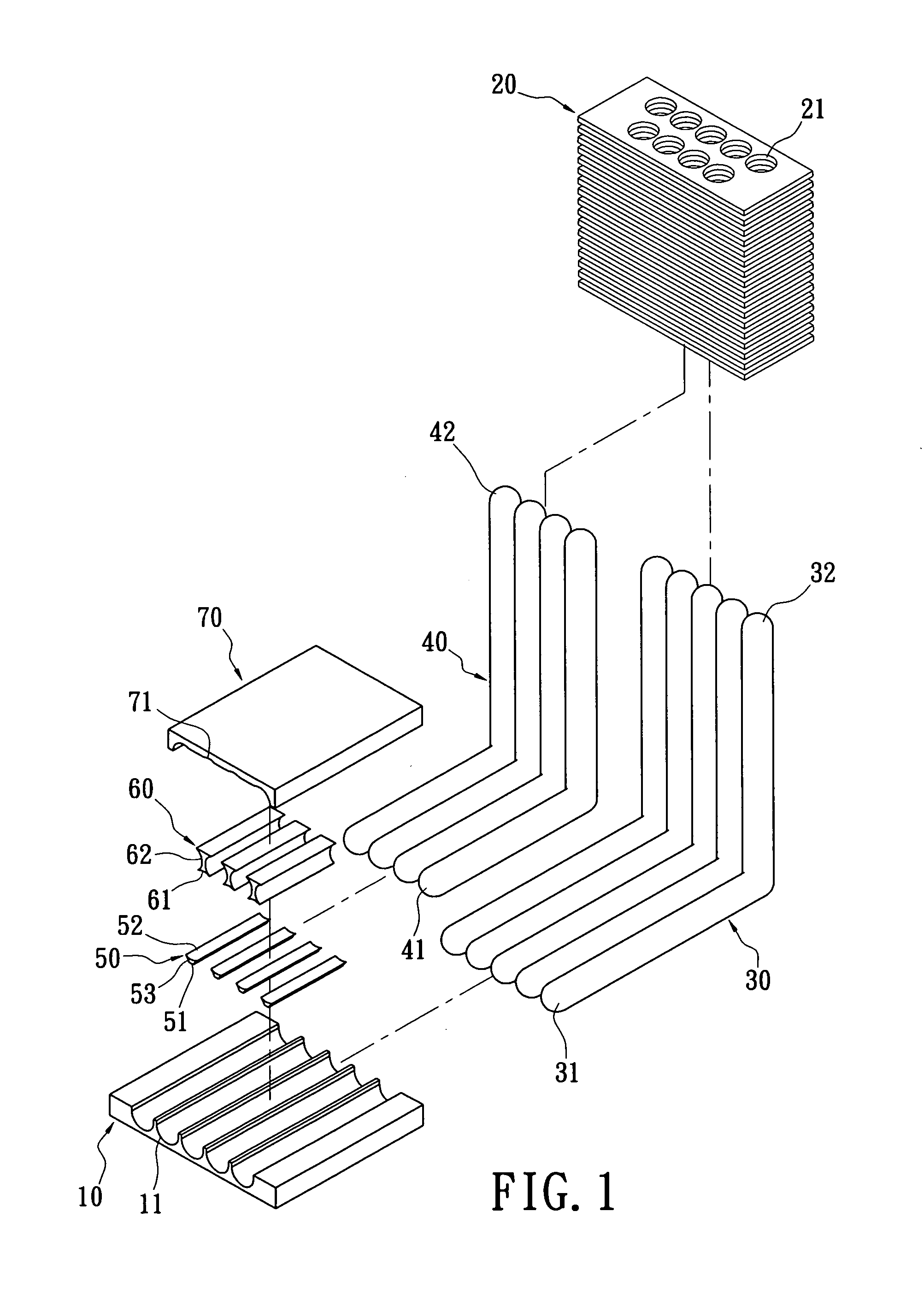
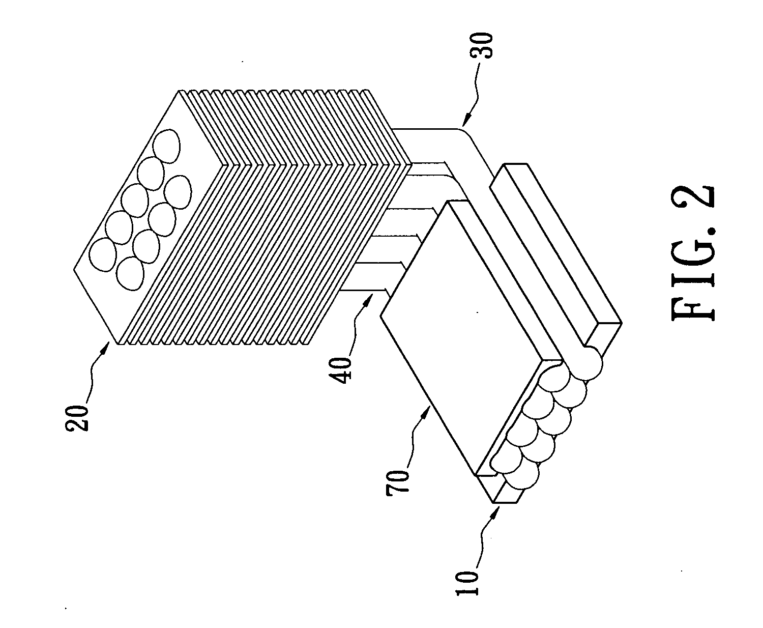
[0023]Reference is made to FIGS. 1˜3, which show the cooling apparatus of the first embodiment of the present invention. The cooling apparatus includes a base 10, a cooler 20, a plurality of first heat pipes 30, a plurality of second heat pipes 40, a plurality of first heat conducting columns 50, a plurality of second heat conducting columns 60, and a cover 70. The base 10 is made of metallic material. The top surface of the base 10 has a plurality of concave slots 11 for being installed with the first heat pipes 30.

[0024]The cooler 20 is a cooing fin set. The cooler 20 has a plurality of through holes 21 for being installed with the first heat pipes 30 and the second heat pipes 40.

[0025]Each of the first heat pipes 30 has a heat-absorbing terminal 31 and a condensing terminal 32. The heat-absorbing terminals 31 of the first heat pipes 30 are installed in the concave slots 11 so that the heat-absorbing terminals 31 of the first heat pipes 30 are disposed on the base 10 spaced at int...


PUM


Abstract

A cooling apparatus includes a base, a plurality of first heat pipes, a plurality of second heat pipes, a plurality of first heat conducting columns and a plurality of second heat conducting columns. Each of the first heat pipes and the second heat pipes respectively has a heat-absorbing terminal. The heat-absorbing terminals of the first heat pipes are disposed on the base spaced at intervals. The heat-absorbing terminals of the second heat pipes are stacked above the heat-absorbing terminals of the first heat pipes spaced at intervals. Each of the first heat conducting columns is installed between the heat-absorbing terminals of the two adjacent first heat pipes. Each of the second heat conducting columns is installed between the heat-absorbing terminals of the two adjacent second heat pipes. Thereby, the heat conducting area is increased within the base, and the cooling efficiency of the cooling apparatus is enhanced.

Description

BACKGROUND OF THE INVENTION[0001]1. Field of the Invention[0002]The present invention relates to a cooling apparatus. In particular, this invention relates to a cooling apparatus that its heat pipes are stacked and heat conducting columns are disposed between the heat pipes so that the heat conducting area is increased.[0003]2. Description of the Related Art[0004]When electric machines or electronic devices are operating, the electronic components often generate a substantial amount of heat. The heat needs to be dissipated so that the electronic components are assured to operate normally and do not suffer damage due to an excessive operating temperature. In case of the CPU in a computer, the processing speed is very high and a lot of heat is generated, which needs to be rapidly dissipated to make the computer operate normally. Therefore, electric machines or electronic devices often have a cooling apparatus to dissipate the heat generated by the electronic components.[0005]The cooli...

Claims


Application Information

Patent Timeline
Patent Type & Authority Applications(United States)
IPC IPC(8): F28F7/00
CPCF28D15/0275H01L21/4882H01L23/427H01L2924/0002H01L2924/00
Inventor CHANG, CHENG-YI
Owner COOLER MASTER CO LTD
Why Eureka
Try Eureka