Imaging apparatus, imaging processing method, and imaging control program

a technology of imaging control and imaging apparatus, which is applied in the field of imaging apparatus, imaging processing method, imaging control program, can solve the problems of saturation unevenness, difficulty in completely eliminating saturation unevenness, and low luminance of sn at a low luminance part of short-exposure-time signal, etc., and achieves wide dynamic range and wide dynamic range

Inactive Publication Date: 2009-06-18
SONY CORP
View PDF4 Cites 34 Cited by
  • Summary
  • Abstract
  • Description
  • Claims
  • Application Information

AI Technical Summary

Benefits of technology

[0014]However, in an imaging apparatus, which widens a dynamic range by synthesizing a long-exposure-time signal and a short-exposure-time signal, there has been a problem in that it is difficult to completely eliminate a phenomenon of saturation unevenness arising in the middle-luminance part by only using peak-clipping processing. In an imaging device of a type of conducting exposure twice in one vertical synchronization period, it is necessary for a short-exposure time to be included within a vertical blanking period. Thus, if it is assumed that a long-exposure time is used as the longest, the ratio of a long-exposure time to a short-exposure time becomes about 20 times or more. Accordingly, the amount of the output signal of the imaging device obtained from a same amount of light becomes different by the ratio of exposure, and thus the short-exposure-time signal has an S/N ratio lower as much as the ratio of exposure.
[0015]Also, if processing is performed by placing emp

Problems solved by technology

However, in an imaging apparatus, which widens a dynamic range by synthesizing a long-exposure-time signal and a short-exposure-time signal, there has been a problem in that it is difficult to completely eliminate a phenomenon of saturation unevenness arising in the middle-luminance part by only using peak-clipping processing.
Also, if processing is performed by placing emphasis on a characteristic of smoothing the grad

Method used


Image

  • Imaging apparatus, imaging processing method, and imaging control program
  • Imaging apparatus, imaging processing method, and imaging control program
  • Imaging apparatus, imaging processing method, and imaging control program

Examples


Embodiment Construction

[0037]In the following, a detailed description will be given of embodiments of the present invention with reference to the drawings. In this regard, the present invention is not limited to the following examples. It goes without saying that any modifications are possible to the present invention without departing from the spirit and scope of the invention.

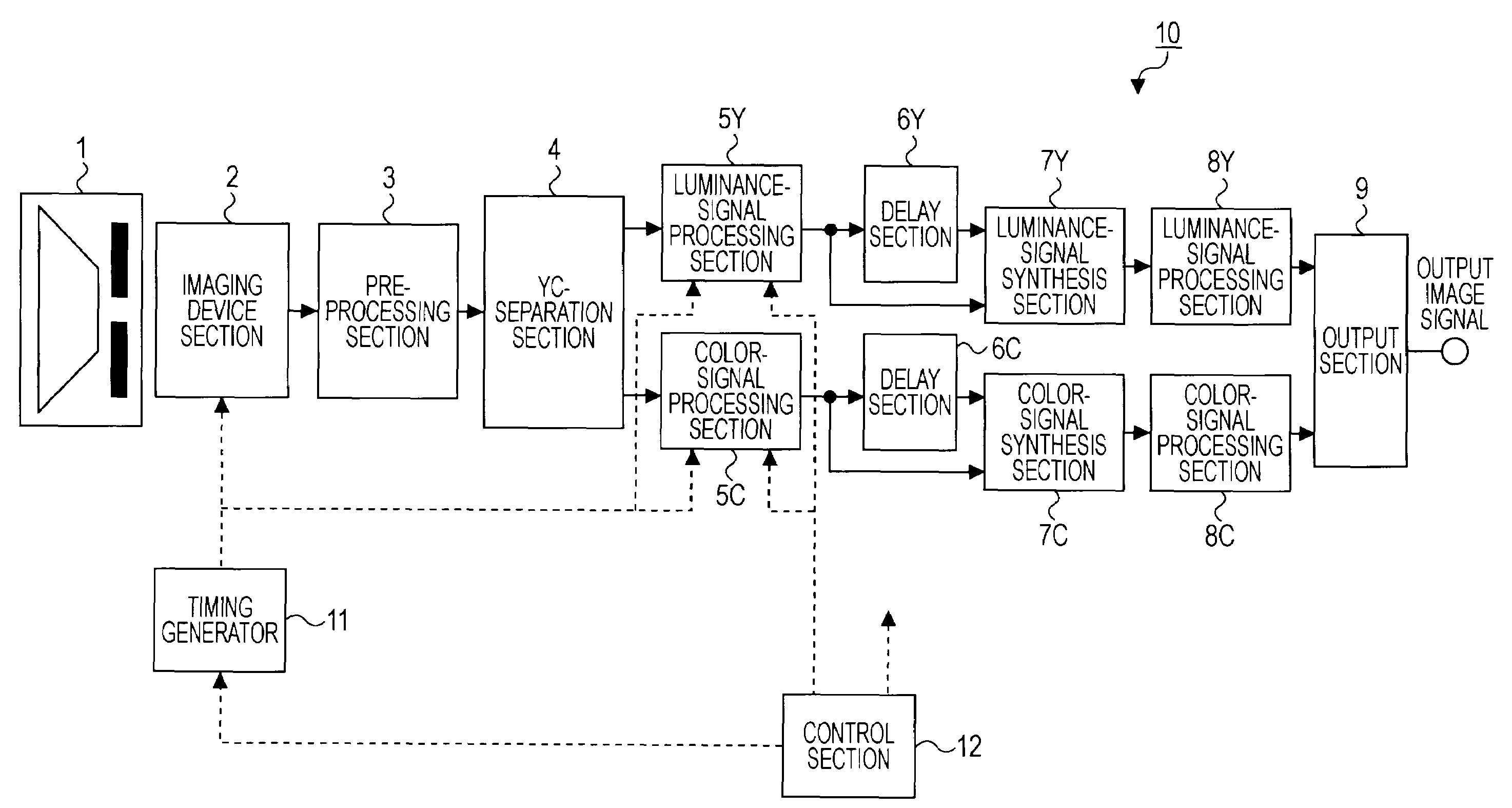
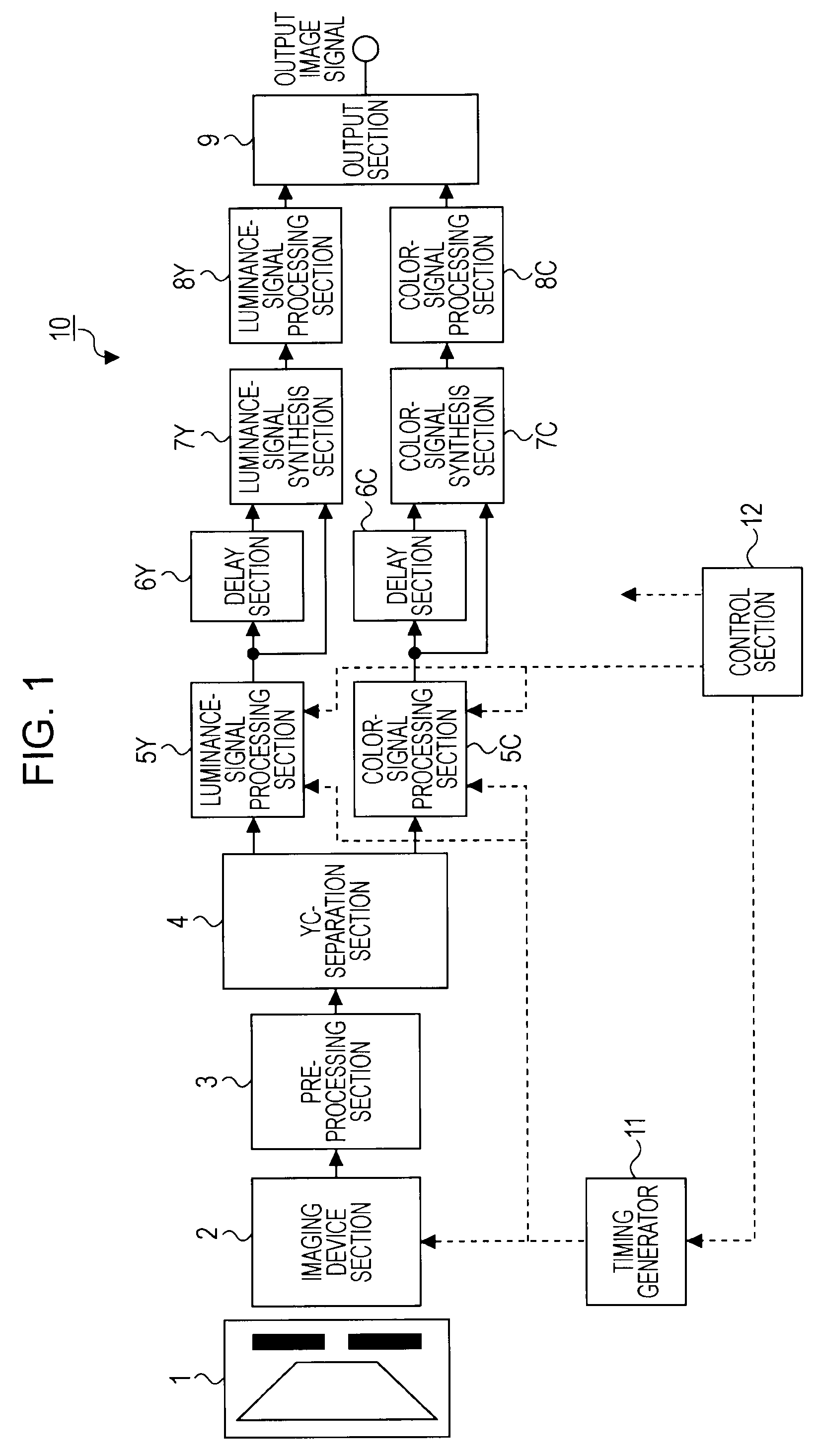
[0038]The present invention is applied to an imaging apparatus 10 having a configuration as shown in FIG. 1, for example.

[0039]The imaging apparatus 10 includes an imaging optical system 1, an imaging device section 2, a pre-processing section 3, a YC-separation section 4, a first luminance-signal processing section 5Y, a first color-signal processing section 5C, delay sections 6Y, 6C, a luminance-signal synthesis section 7Y, a color-signal synthesis section 7C, a second luminance-signal processing section 8Y, a second color-signal processing section 8C, an output section 9, a timing generator 11, a control section 12, etc.

[0040]Th...


PUM


Abstract

An imaging apparatus includes: an imaging device outputting, during a unit period of time, a long-exposure-time image signal having a relatively long exposure time and a short-exposure-time image signal having a relatively short exposure time; a first clipping processing mechanism clipping a part not lower than a first signal level of a luminance signal obtained from the long-exposure-time image signal; a second clipping processing mechanism clipping a part not higher than a second signal level of a luminance signal obtained from the short-exposure-time image signal; and a signal processing mechanism generating a synthesized image signal having a dynamic range wider than dynamic ranges of both of the image signals by synthesizing the clipped image signals, wherein the second signal level is not lower than a signal level obtained by dividing the first signal level by a ratio in time of the long exposure time to the short exposure time.

Description

CROSS REFERENCES TO RELATED APPLICATIONS[0001]The present invention contains subject matter related to Japanese Patent Application JP 2007-326250 filed in the Japanese Patent Office on Dec. 18, 2007, the entire contents of which are incorporated herein by reference.BACKGROUND OF THE INVENTION[0002]1. Field of the Invention[0003]The present invention relates to an imaging apparatus, an imaging method, and an imaging control program which generate a synthesized image signal having a wide dynamic range by synthesizing a long-exposure-time signal and a short-exposure-time signal.[0004]2. Description of the Related Art[0005]In a related-art imaging apparatus using a solid-state imaging device such as a CCD (Charge Coupled Device), etc., the amount of light input (amount of exposure) into an imaging device is adjusted by an aperture and en electronic shutter speed. That is to say, the amount of exposure is decreased when a light scene is shot in order to prevent the occurrence of so-calle...

Claims


Application Information

Patent Timeline
IPC IPC(8): H04N5/235H04N5/243H04N5/335H04N5/353H04N5/355H04N5/357H04N5/372H04N5/374H04N5/378
CPCH04N5/2353H04N5/3722H04N5/35536H04N5/335H04N23/73H04N25/58H04N25/589H04N25/00H04N25/715
Inventor SATOH, YUTAKAASOMA, AKIRA
Owner SONY CORP
Why Eureka
Try Eureka