Image pickup apparatus and display control method for the same

a pickup apparatus and image technology, applied in the field of image pickup apparatus, can solve the problems of user difficulty in quick and accurate manual focus, user difficulty in quickly determining in which direction of close direction and infinity direction, and achieve the effect of easy visual understanding

Inactive Publication Date: 2009-06-18
CANON KK
View PDF9 Cites 57 Cited by
  • Summary
  • Abstract
  • Description
  • Claims
  • Application Information

AI Technical Summary

Benefits of technology

[0007]The present invention provides an image pickup apparatus capable of displaying a focus guide image which is easily understood visually, and its image displaying method.

Problems solved by technology

In this case, unless accustomed to using the split image to a certain extent, a user may find it difficult to perform manual focusing quickly and accurately.
Consequently, a user may find it difficult to quickly determine in which of a close direction and an infinity direction he should perform a manual focusing operation for the object targeted for focusing.

Method used


Image

  • Image pickup apparatus and display control method for the same
  • Image pickup apparatus and display control method for the same
  • Image pickup apparatus and display control method for the same

Examples


embodiment 1

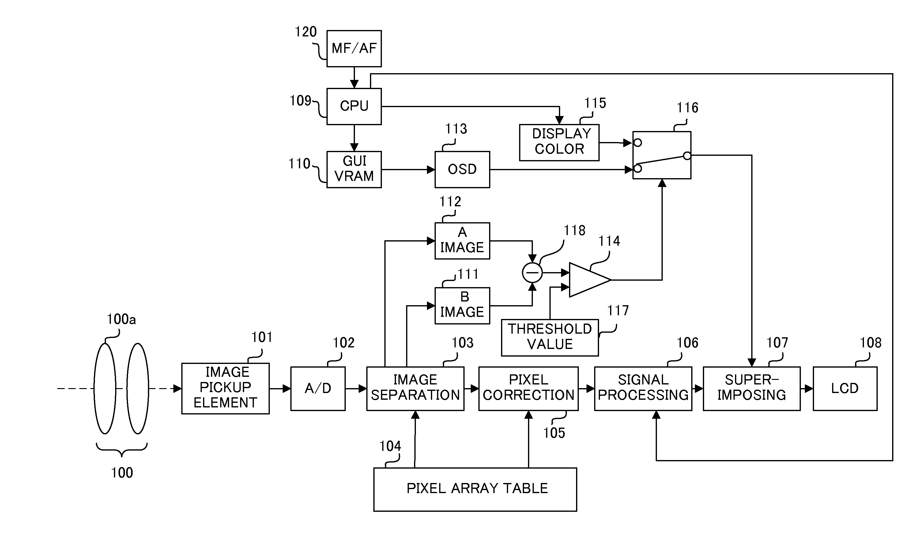
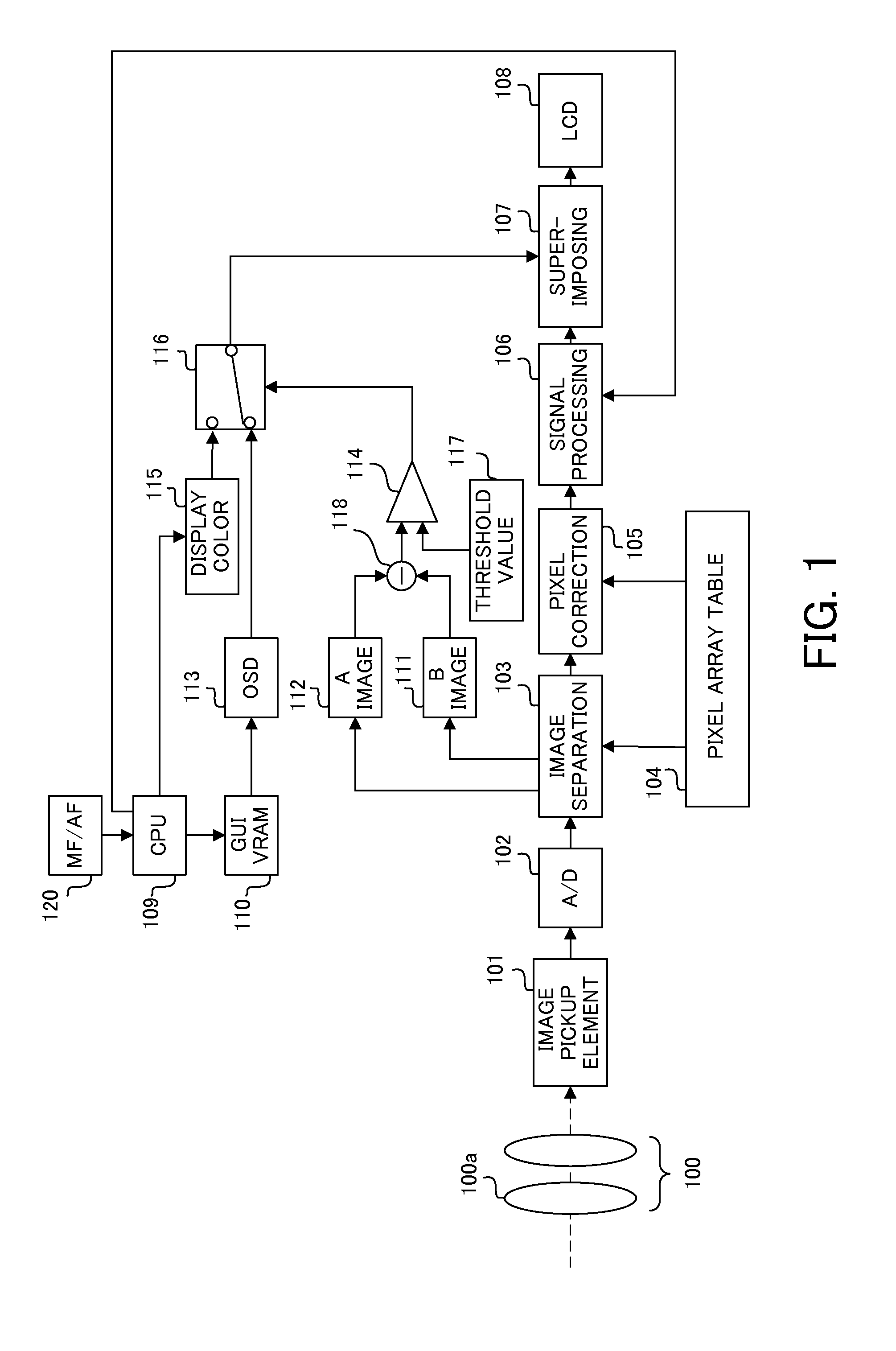
[0054]FIG. 1 shows a configuration of a digital camera (image pickup apparatus) which is Embodiment 1 of the present invention. Digital cameras include a digital still camera and a video camera. In this case, the digital still camera will be described.

[0055]In FIG. 1, reference numeral 100 denotes an image pickup optical system, which includes a focus lens 100a. The image pickup optical system 100 may be detachably attached to a camera main body (not shown) as an interchangeable lens or integrated with the camera main body.

[0056]Reference numeral 101 denotes an image pickup element that includes a CCD sensor or a CMOS sensor, and photoelectrically converts an object image formed by a light flux from the image pickup optical system 100.

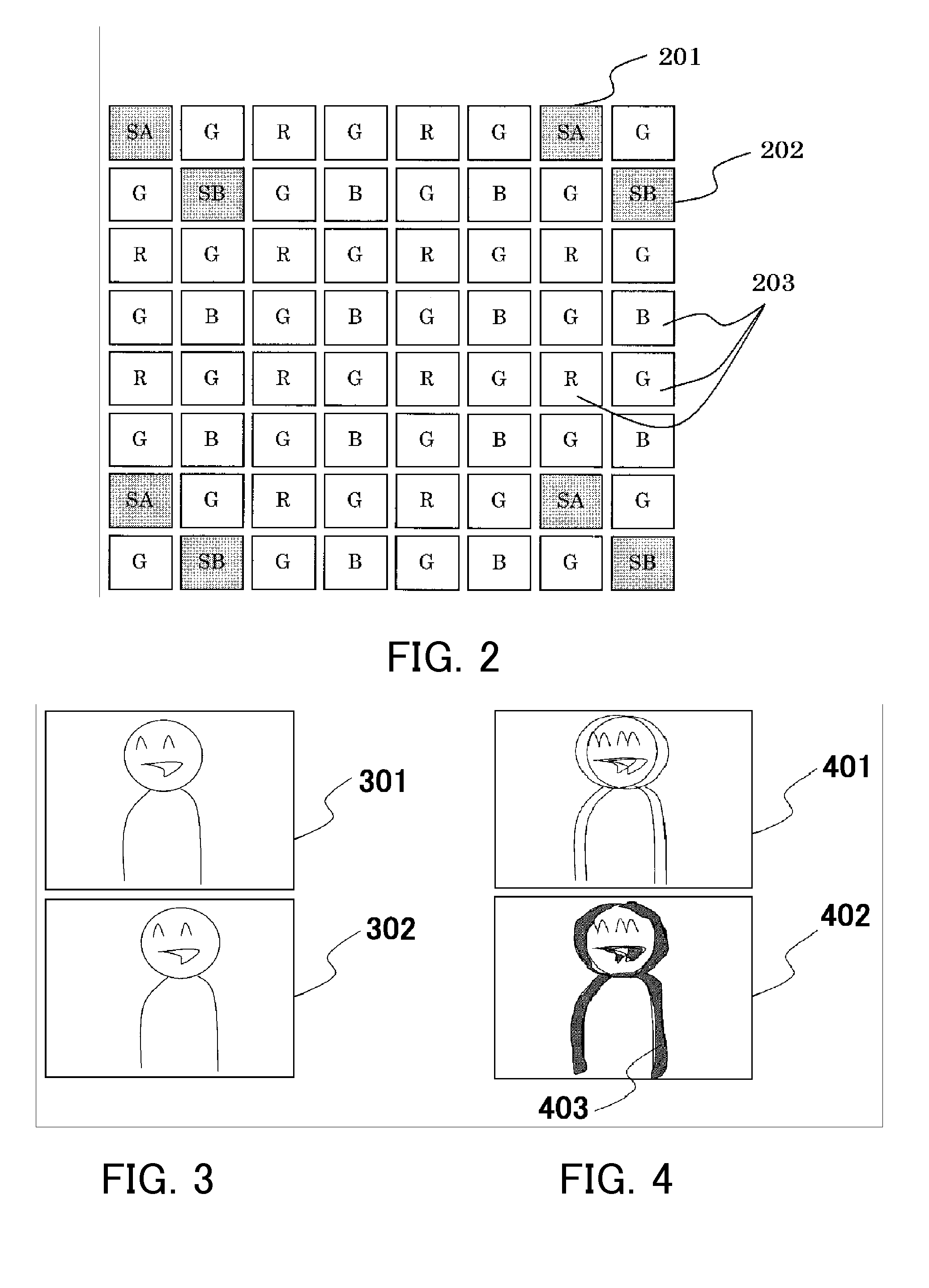
[0057]Referring to FIG. 2, a pixel array in the image pickup element 101 will be described. FIG. 2 shows a partial pixel array in an image pickup plane of the image pickup element 101.

[0058]On the image pickup plane (single image pickup element), a nor...

embodiment 2

[0098]Embodiment 1 has been described by way of case in which the light flux from the image pickup optical system 100 is pupil-divided in the left-and-right direction to form the A and B images. However, the light flux may be pupil-divided in an up-and-down direction to form A and B images.

[0099]The light flux from the image pickup optical system 100 may be pupil-divided in left-and-right and up-and-down directions to form A and B images that make a pair in the left-and-right direction and A and B images that make a pair in the up-and-down direction.

[0100]FIG. 6 shows a circuit structure that compares a displacement amount (difference signal) between each pair of A and B images when the light flux is pupil-divided in the left-and-right and up-and-down directions with the threshold value stored in the threshold value memory 117 shown in FIG. 1 to generate a signal for changing the switch 116. In Embodiment 2, components similar to those of Embodiment 1 are denoted by similar referenc...

embodiment 3

[0107]Embodiment 1 has been described by way of case in which the object area having a difference in displacement amount between the A and B images larger than the threshold value is highlighted as the highlight part. However, inserting an inverter between the output of the comparator 114 and the switch 116 of FIG. 1 enables highlighting of the object area having a difference in displacement amount between the A and B images smaller than the threshold value as a highlight part. As a result, Embodiment 3 enables manual focus guiding that allows a user to clearly recognize an object area of a near-focused state.


PUM


Abstract

An image pickup apparatus of the present invention comprises an image obtaining part configured to photoelectrically convert a first object image and a second object image formed by light fluxes divided by a pupil divider among light fluxes from an image pickup optical system to generate a first image and a second image, a displaying part configured to display images, and a processing part configured to cause the displaying part to display a superimposed image formed by superimposing the first and second images on each other.

Description

BACKGROUND OF THE INVENTION[0001]The present invention relates to an image pickup apparatus such as a digital camera or a video camera, and more particularly to an image pickup apparatus which has a function of displaying a guide image for manual focusing.[0002]Japanese Patent Laid-Open No. 2000-156823 discloses a focus detection method in autofocusing of the image pickup apparatus. According to this focus detection method, a pixel group for focus detection is discretely disposed in an image generation pixel group of an image pickup element, and a light flux from an image pickup optical system is divided (pupil division) by a microlens disposed in the front of the focus detection pixel group to form a pair of object images on the focus detection pixel group. A defocus amount of the image pickup optical system is obtained by detecting a phase difference between the pair of object images.[0003]Each of Japanese Patent Laid-Open Nos. 2001- and 2005-080093 discloses an image pickup appar...

Claims


Application Information

Patent Timeline
Patent Type & Authority Applications(United States)
IPC IPC(8): H04N5/222H04N5/232
CPCG06T11/00H04N5/23293H04N5/23212H04N23/672H04N23/633H04N25/134
Inventor SUZUKI, JUNSATO, YOSHINOBUOGAWA, TAKESHI
Owner CANON KK
Why Eureka
Try Eureka