Device and method for vision test

a vision test and device technology, applied in the field of devices and methods for vision testing, can solve the problems of not being able to return to exactly the same test position, not being able to grade the function level in one and the same neural unit, and difficulty in predicting the function level

Inactive Publication Date: 2009-06-18
VISUMETRICS
View PDF16 Cites 6 Cited by
  • Summary
  • Abstract
  • Description
  • Claims
  • Application Information

AI Technical Summary

Benefits of technology

[0010]The object of the present invention therefore is to provide a device and a method which can be used to diagnose at an early stage disorders affecting the neural units in an eye.
[0016]The source of error caused by the oscillations of the eye during traditional tests is eliminated by the short exposure time.
[0018]Preferably the device comprises a tube. The image surface is arranged at one end of the tube, which means that the other end of the tube is adapted to be the viewing position. A simple optical system is preferably placed in the viewing position to guarantee that the image surface is in the focus of the viewer. Most preferably, the length of the tube is less than 30 cm. This has the advantage that a vision test with the inventive device is relatively easy to arrange. The ease of arrangement is that the device can be placed at will, that is, a large and lightproof room is not required: the tube replaces the room.
[0019]A tube makes it possible to use an SLM (Spatial Light Modulator) as an image surface. There are three main types: transmissive and reflective liquid crystal matrices and reflective micro mirrors (DLP=Digital Light Projection), which are normally used for example in digital projectors. Common examples are LCD matrices (Liquid Crystal Display) and DLP matrices in combination with an external light source, for instance a light bulb or an LED (Light Emitting Diode). It is advantageous to use a laser since the matrix can pass very thin, collimated beams which due to their small cross-sectional areas are very little affected by any defects in the optics of the eye. The width of each matrix is typically about 10-20 mm. Preferably the width is less than 30 mm. The most common number of elements is 1024×768 (XVGA in PC terminology). Thus such an element typically has the size of 25 μm×25 μm. The device and the method according to the invention require luminous points with a maximum width less than or equal to 0.5 minutes of arc, and most preferably about 0.5 minutes of arc. This is achieved with the above-mentioned size of element at a viewing distance of about 0.2 m. An SLM can relatively easily be controlled by an ordinary PC.
[0020]Preferably the matrix / image surface is such that the points can be lighted with optional colours. This has the advantage that several functions of the eye can be checked.

Problems solved by technology

In general it is difficult to predict the function level based on knowledge of receptor density.
By presenting light spots with a smaller diameter than the neural units of the visual system, the unexpected side effect occurs that it will not be possible to return to exactly the same test position.
It is thus not possible to grade the function level in one and the same neural unit.

Method used


Image

  • Device and method for vision test
  • Device and method for vision test
  • Device and method for vision test

Examples


Embodiment Construction

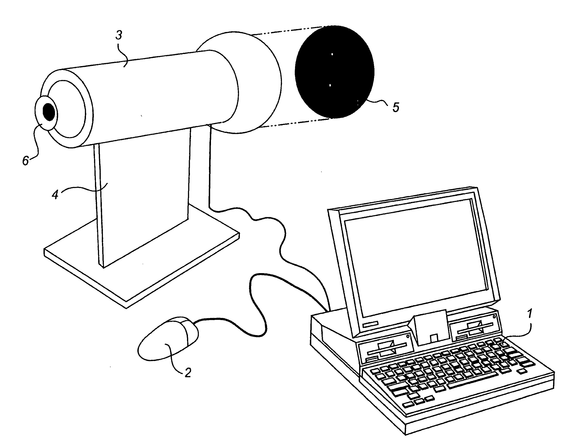
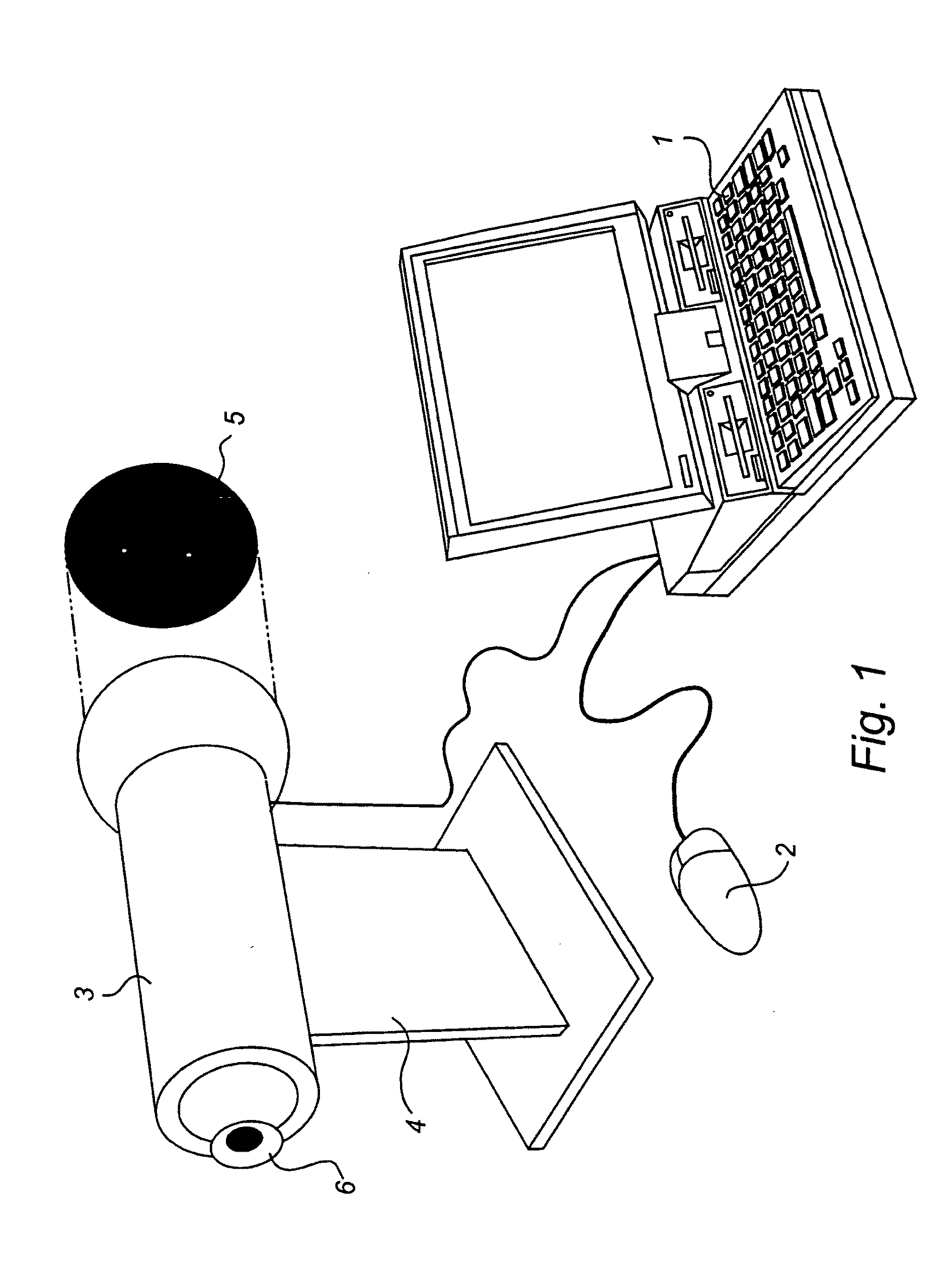
[0027]FIG. 1 shows a vision testing assembly according to an embodiment of the present invention involving a PC 1, including a mouse 2, and a tube 3 on a stand 4. For easy understanding, an example of an image surface 5 with two lighted points is shown extracted from the tube 3. An eye 6 is illustrated in the viewing position.

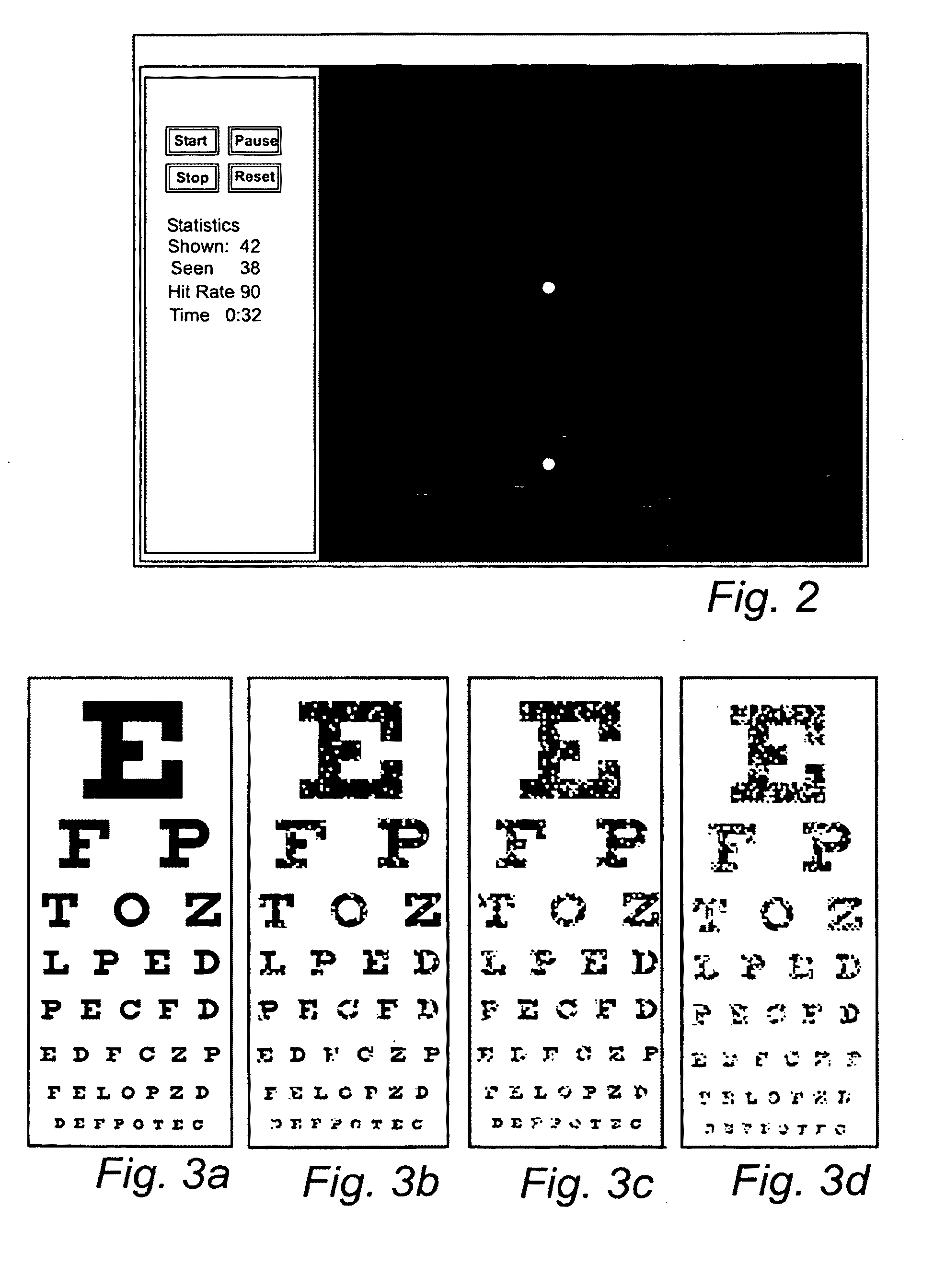
[0028]FIG. 2 shows an example of the display image of the computer during testing. A vision test according to the present invention can be carried out in various ways. One way is to randomly and briefly light one or two points on the image surface and after that briefly light new sets of one or two other points. This is repeated until a sufficient number of points on the image surface have been lighted. The time during which a certain point is lighted should be less than 0.2 s, which is the latency of actively searching eye movements. Parallel to the above-described process, a viewer / patient registers by clicking the mouse how many points he has observed. By li...


PUM


Abstract

A device for vision testing comprises a viewing position (6) and an image surface (5). The distance between the viewing position (6) and the image surface (5) is enclosed. The relation between the resolution of the image surface and the distance between the viewing position (6) and the image surface (5) is such that the angle of a point on the image surface (5) is less than or equal to 1 minute of arc seen from the viewing position (6).

Description

FIELD OF INVENTION[0001]The invention relates to a device and a method for vision testing, comprising a viewing position and an image surface, the distance between the viewing position and the image surface being enclosed.BACKGROUND ART[0002]Testing of the central vision (“in the line of sight”) is necessary for diagnosing and following up a wide spectrum of disorders which either destroy, disturb, or disconnect the neural units that make up the visual system. Examples of such disorders include inflammations and degenerations in the macula of the retina, inflammations in the visual nerve, such as multiple sclerosis, and tumour formations pressing against, for instance, the optic nerve or optic chiasm, such as pituitary tumours. In the following the need for improved diagnostics will be developed in more detail using a common disorder as an example.[0003]There is a rapidly increasing number of individuals all over the world with double-sided visual loss due to degeneration of the mac...

Claims


Application Information

Patent Timeline
Patent Type & Authority Applications(United States)
IPC IPC(8): A61B3/02A61B3/00
CPCA61B3/032
Inventor FRISEN, LARS
Owner VISUMETRICS
Why Eureka
Try Eureka