Inductive Flashlight Charging System with Concentric Coils

a charging system and inductive technology, applied in the field of inductive flashlight charging system, can solve the problems of affecting the effect of the light source, and requiring a large amount of adjustment, so as to achieve the effect of maximizing the interfacing area, and not affecting the design of the reflector

Inactive Publication Date: 2009-06-18
PENTAGONLIGHT
View PDF11 Cites 8 Cited by
  • Summary
  • Abstract
  • Description
  • Claims
  • Application Information

AI Technical Summary

Benefits of technology

[0013]A rechargeable flashlight uses induction for charging, and thus does not utilize external contacts. The flashlight is cylindrically shaped, and has a secondary coil wrapped around a portion of the cylindrical body. The flashlight is placed within a ring shaped charger with a primary coil, such that the primary coil is wrapped around the secondary coil. This greatly

Problems solved by technology

The tight holding of the grabbing arms often cause difficulties in manipulating the flashlight to make the proper alignment.
Since the contacts are usually under the flashlight and hidden from the view, the mating of the contacts often requires repeated attempts and a great deal of adjustment.
This nuisance prolongs the charger attachment process and often frustrates the user.
The introduction of electrical contacts increases the engineering design challenge.
Despite much effort towards improving the contact design, since the contacts are externally placed, the electrical contacts deteriorate over the lifespan of the flashlight.
This causes increasing poor contact mating over time, and thus reduced electrical conduct efficiency.
Placing metallic contacts externally where the contacts are connected to the internal battery can p

Method used


Image

  • Inductive Flashlight Charging System with Concentric Coils
  • Inductive Flashlight Charging System with Concentric Coils
  • Inductive Flashlight Charging System with Concentric Coils

Examples


Embodiment Construction

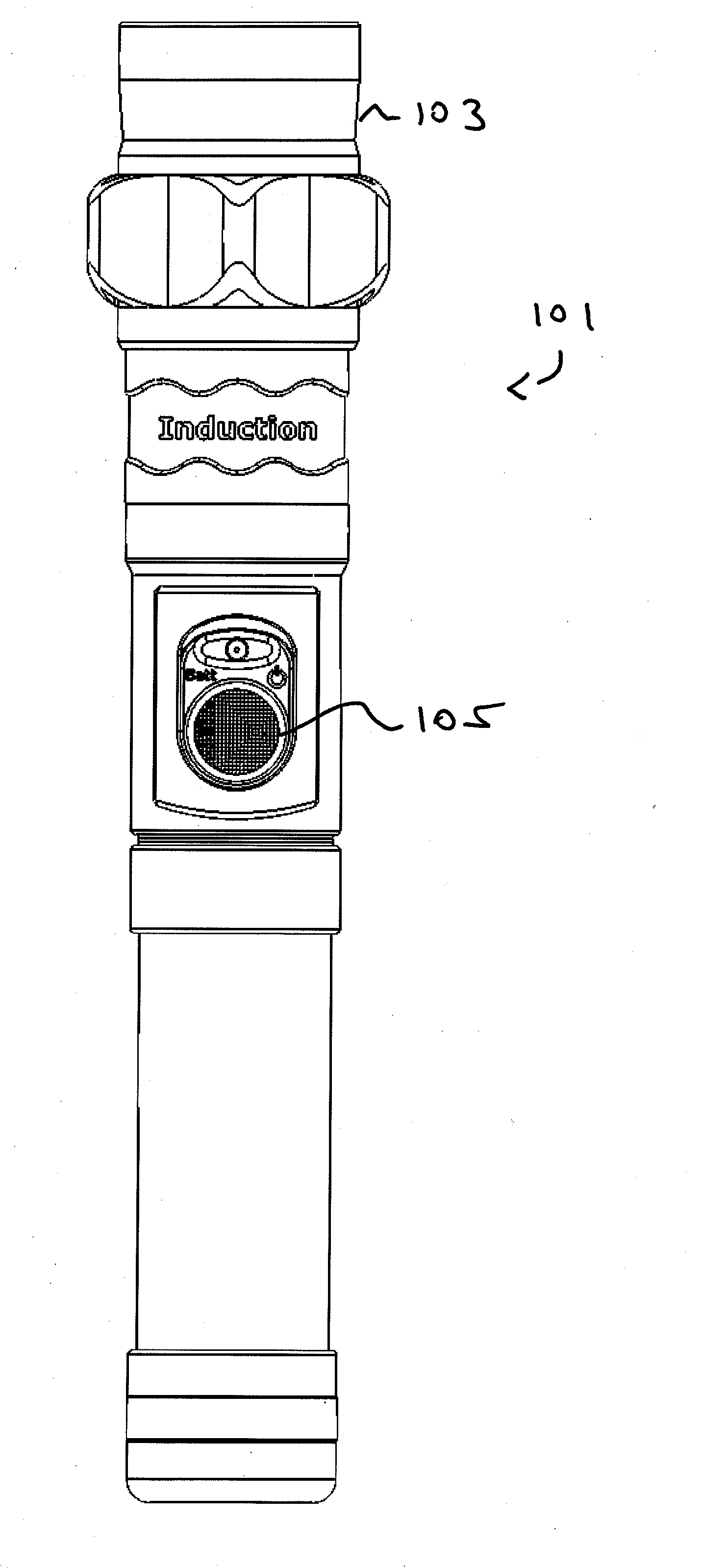
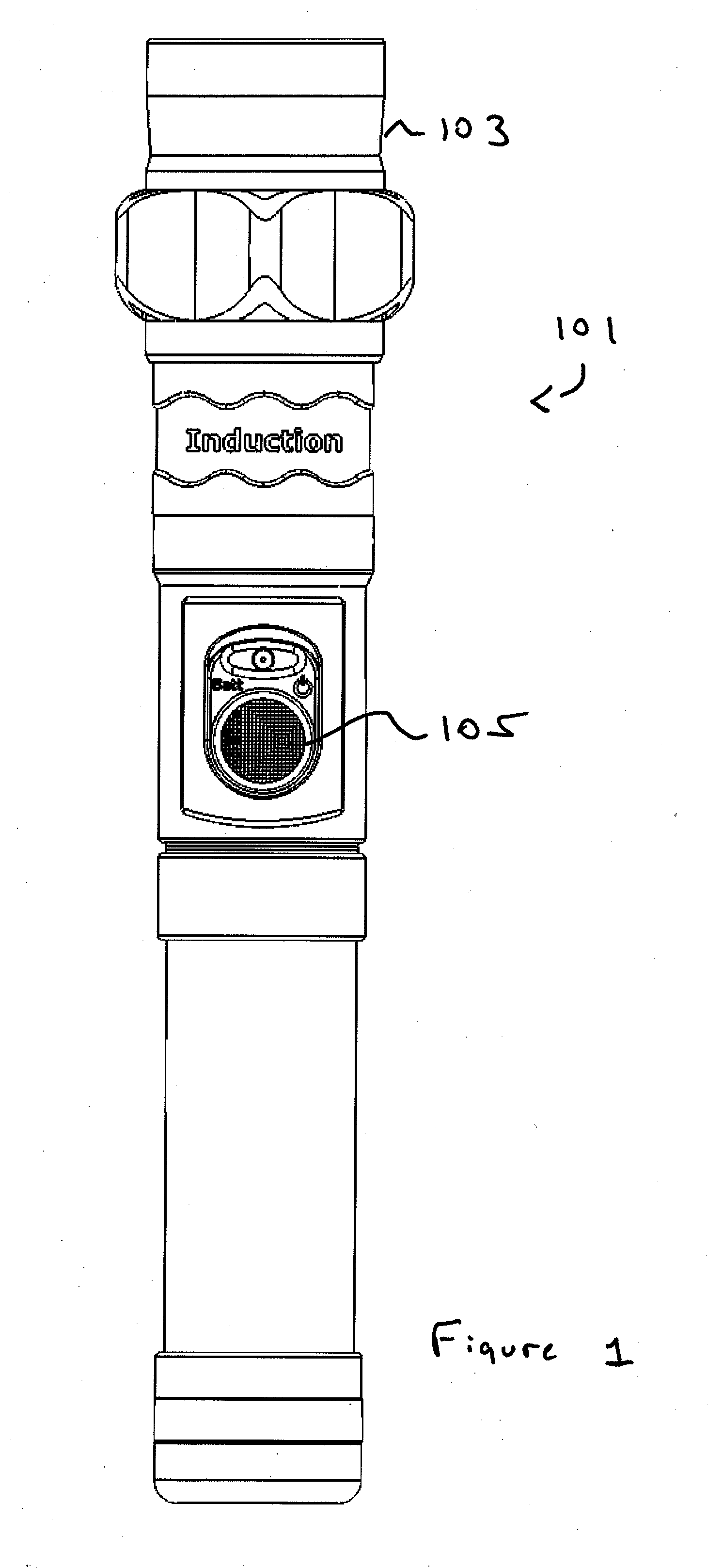
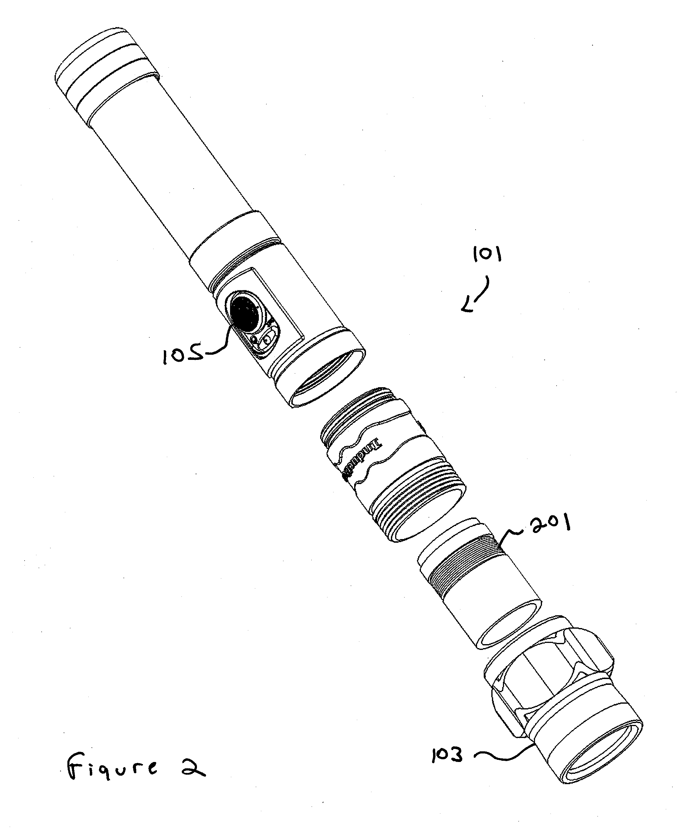
[0024]FIG. 1 illustrates a flashlight 101 that can be charged with induction, which does not require any contact points on the flashlight 101 or the charger 301, and thus does not have any contact points exposed, according to one embodiment of the present invention. The section below the head 103 and above the switch 105 contains the secondary coil 201 for charging. In FIG. 2, the secondary coil 201 in the flashlight 101 is shown. As illustrated in FIG. 2, the secondary coil 201 is positioned in a circumference around the body of the flashlight 101.

[0025]FIG. 3 illustrates a corresponding charger 301, according to one embodiment of the present invention. As illustrated, the primary coil 303 is positioned in the charger 301 for charging the flashlight 101. FIG. 4 illustrates the flashlight 101 placed inside the charging system, according to one embodiment of the present invention. The flashlight 101 is inserted from the top into the charger 301. When the flashlight 101 is placed in t...


PUM


Abstract

A rechargeable flashlight uses induction for charging, and thus does not utilize external contacts. The flashlight is cylindrically shaped, and has a secondary coil wrapped around a portion of the cylindrical body. The flashlight is placed within a ring shaped charger with a primary coil, such that the primary coil is wrapped around the secondary coil. This greatly maximizes the amount of interfacing area between the two coils, without adversely affecting the reflector design. This allows for the charging of a high powered flashlight, without requiring the flashlight to have a disadvantageously sized or constructed head. Furthermore, the primary coil of the charger can advantageously serve as a mechanical support for the flashlight.

Description

TECHNICAL FIELD[0001]This invention pertains generally to flashlight technology, and more specifically to an improved inductive flashlight charging system.BACKGROUND ART[0002]A flashlight is an essential tool for law enforcement officers. As part of an officer's duty gear, a flashlight provides an illumination source that can be critical during night shifts or when entering buildings and other potentially dark spaces. A rechargeable flashlight is preferred over a non-rechargeable flashlight for law enforcement applications, as an officer's flashlight is typically used on a daily basis. A rechargeable flashlight can be fully charged at the beginning of a duty shift. As the law enforcement officer is gearing up, the flashlight is “topped off” and ready for use when the officer goes on duty.[0003]Most rechargeable flashlights require a separate charging unit. The charging unit can be a receptacle for the flashlight, such that when the flashlight is placed in the receptacle, the interna...

Claims


Application Information

Patent Timeline
IPC IPC(8): F21L4/08H02J7/00
CPCH02J7/025F21L4/085H02J7/0045H02J7/0044H02J50/10
Inventor HUANG, JOHN
Owner PENTAGONLIGHT
Why Eureka
Try Eureka