Terminal apparatus, base station, radio communication method and program storage medium

a technology of terminal equipment and base station, which is applied in the direction of wireless communication, wireless commuication services, baseband system details, etc., can solve the problems of large circuit load, time delay, and deterioration of throughpu

Inactive Publication Date: 2009-06-18
KK TOSHIBA
View PDF3 Cites 55 Cited by
  • Summary
  • Abstract
  • Description
  • Claims
  • Application Information

AI Technical Summary

Benefits of technology

[0049]According to an aspect of the present invention, there is provided with a communication method performed by a base station which communicates with a terminal apparatus, the terminal apparatus estimating a state of a channel to obtain an estimated state value of the channel and calculating a correlation between the estimated state value and each of candidates selected from a codebook which includes channel state values to detect a candidate having a high correlation with the estimated state value, comprising:
[0050]measuring quality of a channel between the base station and the terminal apparatus;

Problems solved by technology

When performing feedback, sending a channel as is results in a very large load on the circuit.
That is, every time each terminal receives a signal and estimates a channel response, matching (correlation calculation) should be performed 2B times, the amount of calculation of which constitutes a large load and may eventually produce a time delay and also cause throughput to deteriorate.

Method used


Image

  • Terminal apparatus, base station, radio communication method and program storage medium
  • Terminal apparatus, base station, radio communication method and program storage medium
  • Terminal apparatus, base station, radio communication method and program storage medium

Examples


first embodiment

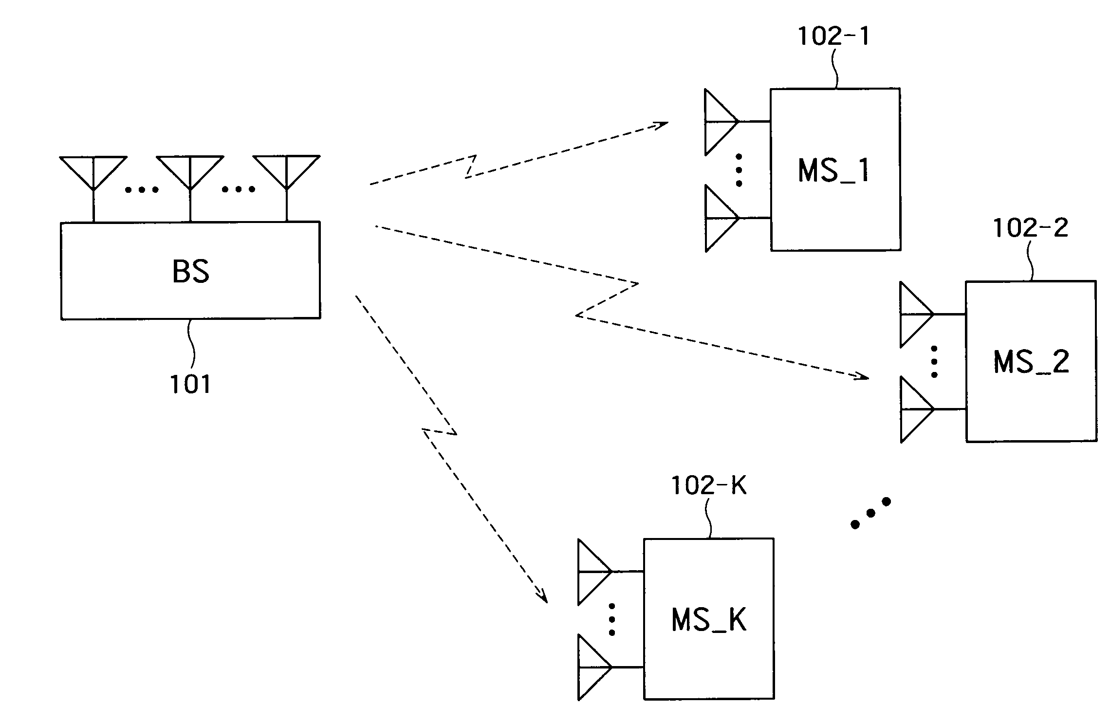
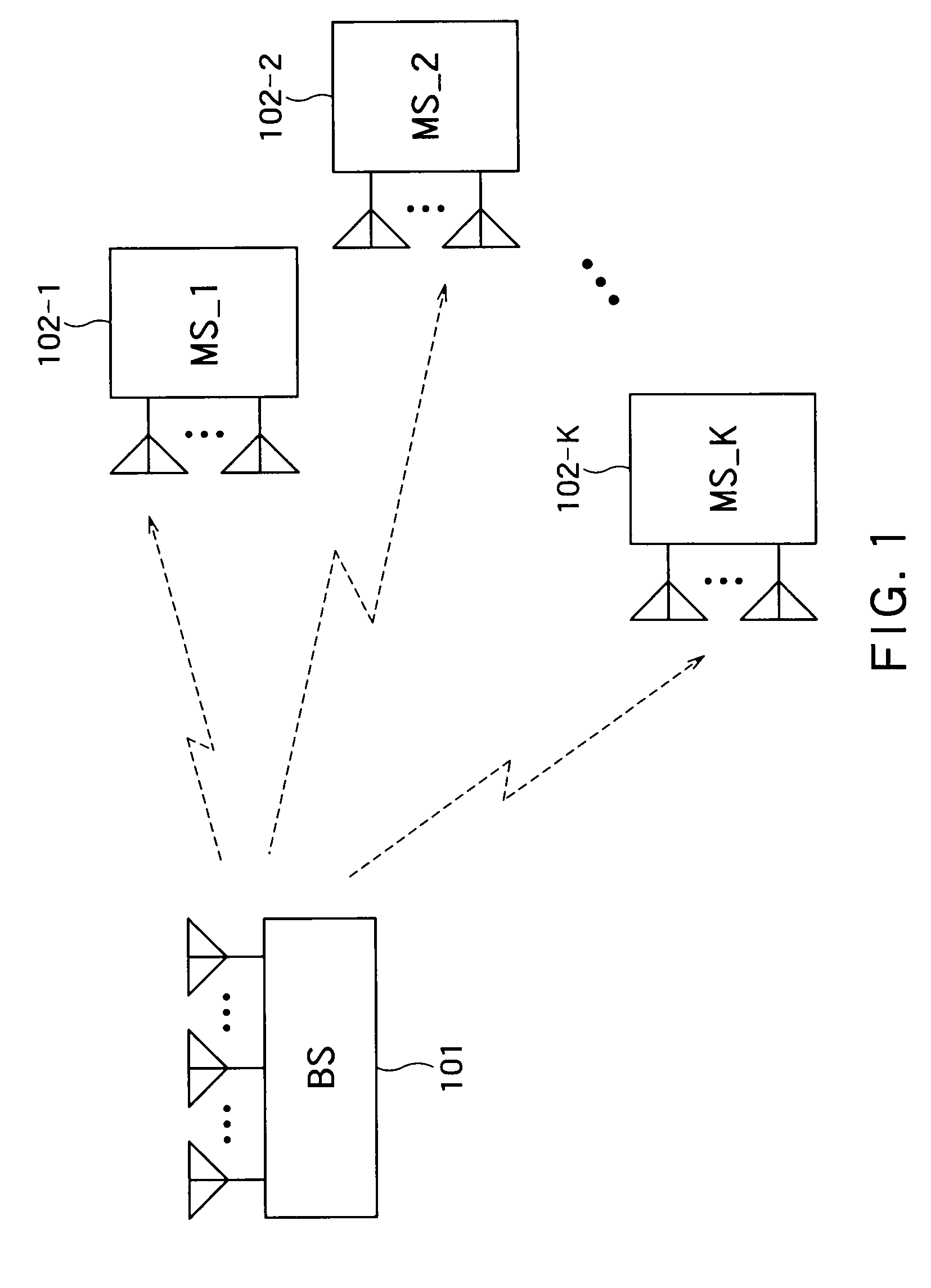
[0079]This embodiment assumes a case where a MIMO-SDMA (Multiple Input Multiple Output-Spatial Division Multiple Access) scheme is used over a downlink in a radio communication system constructed of a base station mounted with an array antenna made up of M antenna elements and K terminal apparatuses (hereinafter simply referred to as “terminals”) mounted with Nk antenna elements (k=1, . . . , K). Furthermore, suppose a signal with Lk streams is sent to a kth terminal. Here, there is a relationship of Lk≦Nk.

[0080]FIG. 1 schematically shows a radio communication system constructed of one base station mounted with M antenna elements and a plurality of terminals mounted with Nk antenna elements. Here, a radio communication within a single cell will be considered and one base station 101 communicates with a plurality of terminals 102-1, 102-2, . . . 102-K. Furthermore, a Frequency Division Duplex (FDD) system is assumed and suppose the base station 101 always acquires information on chan...

second embodiment

[0109]In the first embodiment, a codebook is made up of channel response values (here, phase components), but this embodiment has a feature that a codebook is made up of transmission weight values. Hereinafter, this embodiment will be explained in detail.

[0110]FIG. 6 schematically shows the configuration of a terminal according to the second embodiment. A radio signal received at antenna elements 601-1, 601-2, . . . 601-N is inputted to a channel estimation unit 603 through radio reception units 602-1, 602-2, . . . 602-N. Here, at a kth terminal, the signal received at the respective antenna elements 601-1, 601-2, . . . 601-N is expressed by above described Expression 1.

[0111]The channel estimation unit 603 calculates an estimated value Hest(k) of a channel response matrix H(k) from the received signal expressed by above described Expression 1.

[0112]A symbol detection unit 604 calculates an estimated value sest(k) of a transmission signal s(k) using the channel response matrix Hest(...

third embodiment

[0133]In the first embodiment, the base station side measures quality parameters indicating quality of a channel, but this embodiment has a feature that the quality parameters are measured on the terminal side. Hereinafter, this embodiment will be explained in detail.

[0134]FIG. 9 schematically shows the configuration of a terminal in this embodiment. A radio signal received at antenna elements 901-1, 901-2, . . . 901-N is inputted to a channel estimation unit 903 through radio reception units 902-1, 902-2, . . . 902-N. Here, at a kth terminal, the signals received at the respective antenna elements 901-1, 901-2, . . . 901-N are expressed by above described Expression 1.

[0135]The channel estimation unit 903 calculates an estimated value Hest(k) of a channel response matrix H(k) from the received signal expressed by above described Expression 1. The number of columns of the channel response matrix Hest(k) corresponds to the number of streams transmitted to the kth terminal.

[0136]A sym...


PUM


Abstract

A terminal apparatus includes: a reception unit configured to receive a signal from a base station; a channel estimation unit configured to estimate a state of a channel based on a received signal; a storage configured to store a codebook including channel state values; an index of search number acquisition unit configured to acquire index of search number of candidates to be selected from among the channel state values for a correlation calculation with the estimated state value; a candidate selecting unit configured to select candidates for which the correlation calculation should be performed from among the channel state values according to the index of search number; a correlation calculation unit configured to calculate a correlation between the estimated state value and each of selected candidates; a selection unit configured to select a candidate having a highest correlation value; and a reporting unit configured to report a selected candidate to the base station.

Description

CROSS REFERENCE TO RELATED APPLICATIONS[0001]This application is based upon and claims the benefit of priority from the prior Japanese Patent Applications No. 2007-326395, filed on Dec. 18, 2007; the entire contents of which are incorporated herein by reference.BACKGROUND OF THE INVENTION[0002]1. Field of the Invention[0003]The present invention relates to a terminal apparatus that feeds back information on a channel to a base station, the base station that communicates with the terminal apparatus, a radio communication method executed by the terminal apparatus and base station and a program storage medium storing a communication program.[0004]2. Related Art[0005]In a Multiple Input Multiple Output (MIMO) communication with a plurality of antennas arranged in both a transmitter and a receiver, downlink transmission from a base station to a terminal apparatus (hereinafter simply referred to as a “terminal”) in particular will be thought of. In a closed loop MIMO communication, when a...

Claims


Application Information

Patent Timeline
Patent Type & Authority Applications(United States)
IPC IPC(8): H04B7/216
CPCH04B7/0417H04L25/0204H04L25/0228H04L2025/03802H04L25/03343H04L2025/03426H04L25/0242
Inventor KIKUCHI, SHOHEITANABE, YASUHIKO
Owner KK TOSHIBA
Why Eureka
Try Eureka