
Combination axial-flow fan

Inactive Publication Date: 2009-06-18
TAIWEI FAN TECH
View PDF3 Cites 58 Cited by
  • Summary
  • Abstract
  • Description
  • Claims
  • Application Information

AI Technical Summary

Benefits of technology

[0005]The present invention has been accomplished under the circumstances in view. It is therefore one object of the present invention to provide a combination axial-flow fan, which has the fan hub and the fan blades separately made and then assembled together so that the front edge of one fan blade is suspended above the rear edge of another fan blade, no gap is seen between each two adjacent fan blades when viewed from the front side, and has high wind pressure, high wind capacity, and low noise level characteristics.

Problems solved by technology

However, this design is not applicable due to technical problems in molding technology.
A partial fan blade overlapping arrangement will result in a mold stripping problem after injection molding.
It also tends to cause an insufficient wind pressure problem, which presents difficulties in satisfying heat dissipation requirements of modern electronic devices.

Method used


Image

  • Combination axial-flow fan
  • Combination axial-flow fan
  • Combination axial-flow fan

Examples


Embodiment Construction

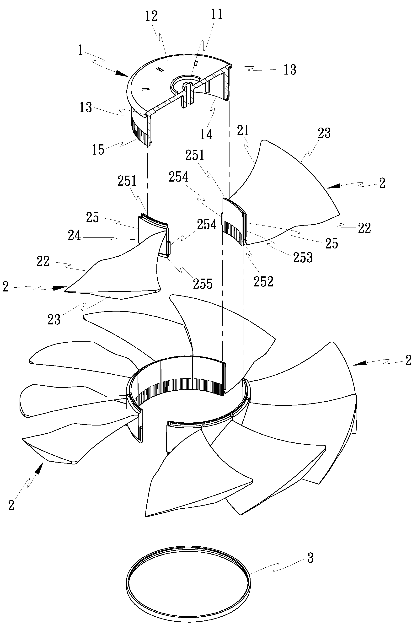
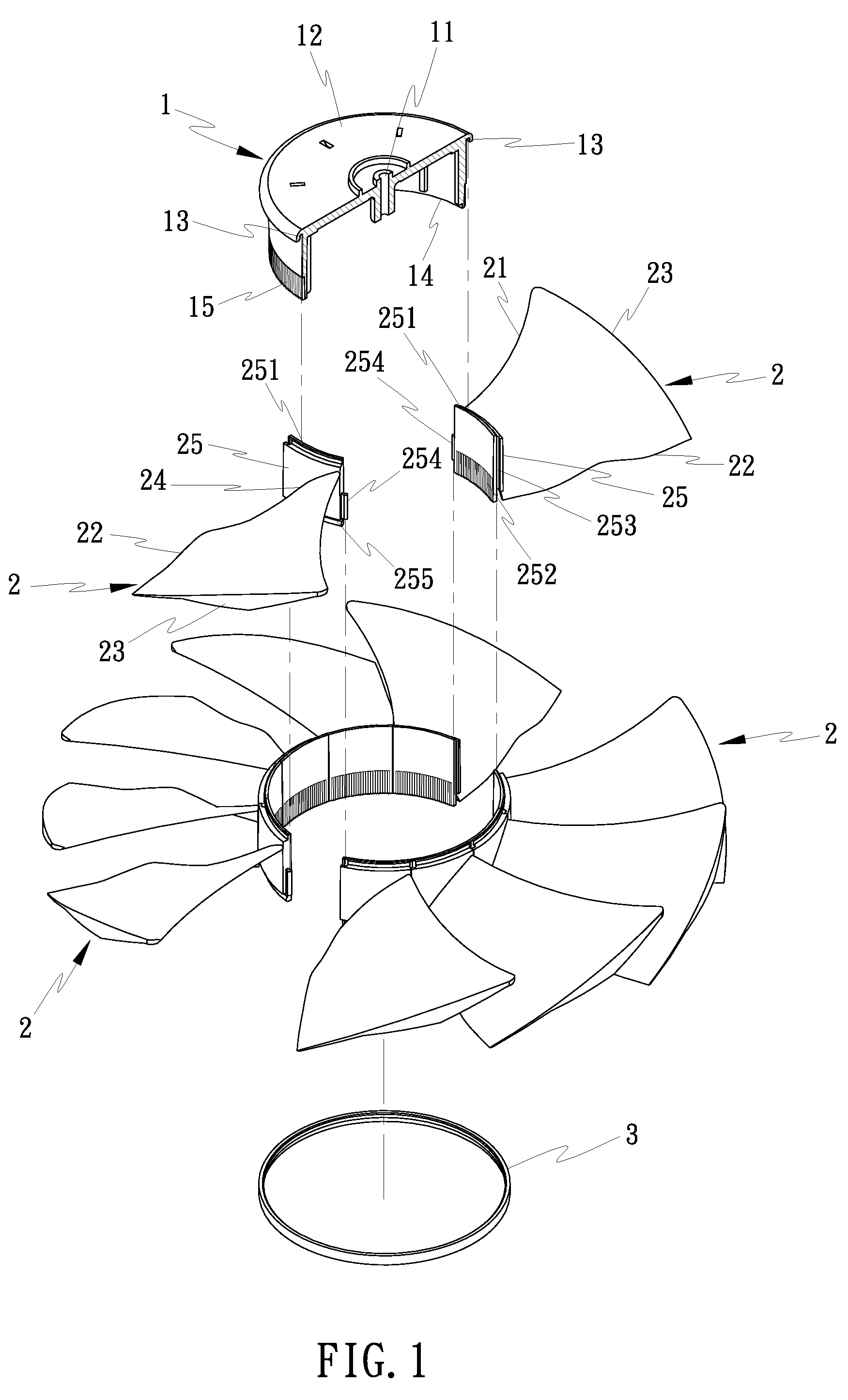
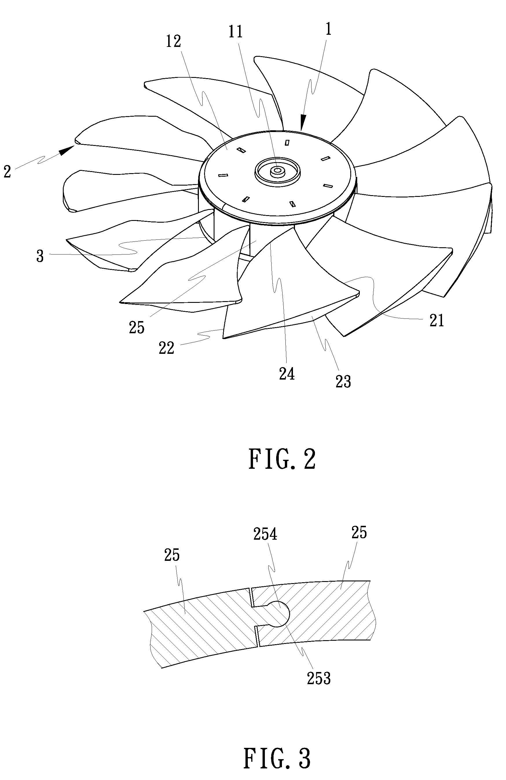
[0013]With reference to FIGS. 1 and 2, a combination axial-flow fan in accordance with the present invention comprises a fan hub 1 and a plurality of fan blades 2. The fan hub 1 and the fan blades 2 are separately molded from plastics by means of injection molding, and then assembled together for use as an active heat dissipation device for the cooling of an electronic product.

[0014]Referring to FIGS. 1 and 2 again, the fan hub 1 may be made in any of a variety of shapes. According to the present preferred embodiment, the fan hub 1 is shaped like a round cap, having a front side 12, a rear side 14, a center connection portion 11 at the center of the front side 12 for the connection of the shaft of a fan motor (not shown), an endless mounting groove 13 extending around the periphery near the front side 12 and having its open side extending in direction from the front side 12 toward the rear side 14, and positioning teeth 15 arranged around the periphery near the rear side 14. The pos...


PUM


Abstract

A high-performance low-noise combination axial-flow fan includes a fan hub that has a center connection portion for the connection of a fan motor shaft and a mounting groove extending around the periphery, and fan blades each having a wedge block disposed at the inner end for fastening to the mounting groove to secure the respective fan blade to the fan hub in such a manner that no gap is seen between each two adjacent fan blades when viewed from the front side.

Description

BACKGROUND OF THE INVENTION[0001](a) Field of the Invention[0002]The present invention relates to a fan and, more particularly, to a combination axial-flow fan for use in an electronic product for forced air convection cooling.[0003](b) Description of the Prior Art[0004]Regular cooler modules are designed for use in electronic and photoelectric products to expel waste heat. A typical conventional cooler module is comprised of a passive heat dissipation device and an active heat dissipation device. A passive heat dissipation device can be a heat sink extruded from copper or aluminum and having multiple radiation fins. An active heat dissipation device can be an axial-flow fan that forces surrounding air to cause convection, thereby lowering the surrounding temperature. A typical conventional axial-flow fan comprises a fan hub 10 and multiple blades 20 integrated into and extending around the periphery of the fan hub 10 (see FIG. 6). By means of controlling a motor to rotate the fan h...

Claims


Application Information

Patent Timeline
IPC IPC(8): B63H1/20
CPCF04D29/329F04D29/646F04D29/34F04D25/0613
Inventor YU, CHIEN-CHUN
Owner TAIWEI FAN TECH
Features
  • Generate Ideas
  • Intellectual Property
  • Life Sciences
  • Materials
  • Tech Scout
  • Unparalleled Data Quality
  • Higher Quality Content
  • 60% Fewer Hallucinations
Learn More