Super regenerative receiver and method of saving power of the same

a super regenerative receiver and receiver technology, applied in the field of super regenerative receivers, can solve the problems that current receiver architectures cannot meet such a low power requirement without degrading sensitivity, and synchronous super regenerative receivers have difficulty in further reducing power consumption with currently available technologies, so as to achieve the effect of reducing power consumption

Active Publication Date: 2009-06-18
ELECTRONICS & TELECOMM RES INST +1
View PDF6 Cites 26 Cited by
  • Summary
  • Abstract
  • Description
  • Claims
  • Application Information

AI Technical Summary

Benefits of technology

[0015]According to another aspect of the present invention, there is provided a method of reducing power consumption of a super regenerative receiver comprising an oscillator having a start-up time period starting oscillation that varies according to an existence of an input signal, wherein the method comprises: controlling power by supplying the power to the super regenerative receiver within the start-up time period of the oscillator.

Problems solved by technology

However, current receiver architectures cannot meet such a low power requirement without degrading sensitivity.
Conventional general super regenerative receivers and synchronous super regenerative receivers have difficulties in further reducing power consumption with currently available technologies.

Method used


Image

  • Super regenerative receiver and method of saving power of the same
  • Super regenerative receiver and method of saving power of the same
  • Super regenerative receiver and method of saving power of the same

Examples


Embodiment Construction

[0023]The present invention will now be described more fully with reference to the accompanying drawings, in which exemplary embodiments of the invention are shown. Like reference numerals refer to the like elements throughout. In this regard, the present embodiments may have different forms and should not be construed as being limited to the descriptions set forth herein. Accordingly, the embodiments are merely described below, by referring to the figures, to explain aspects of the present invention.

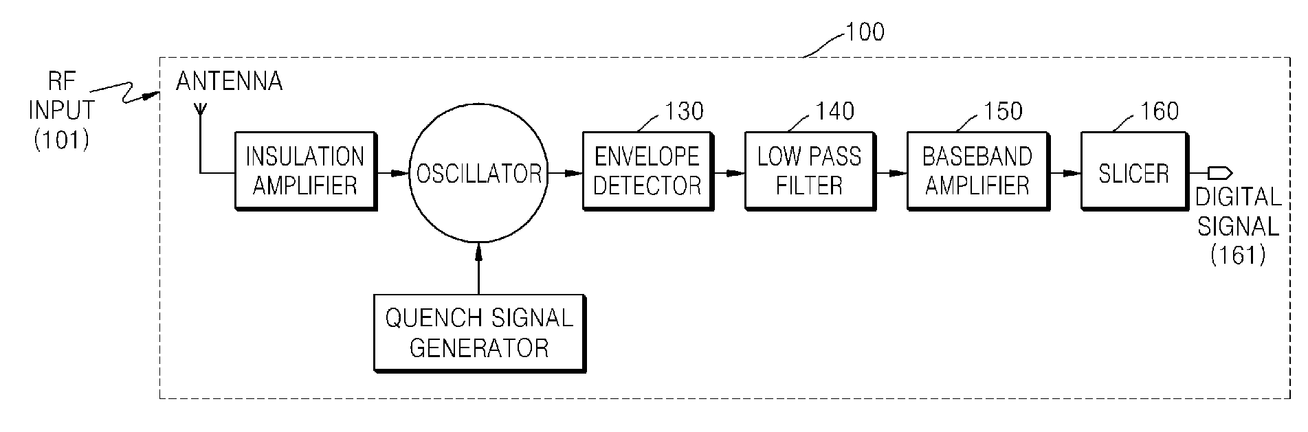
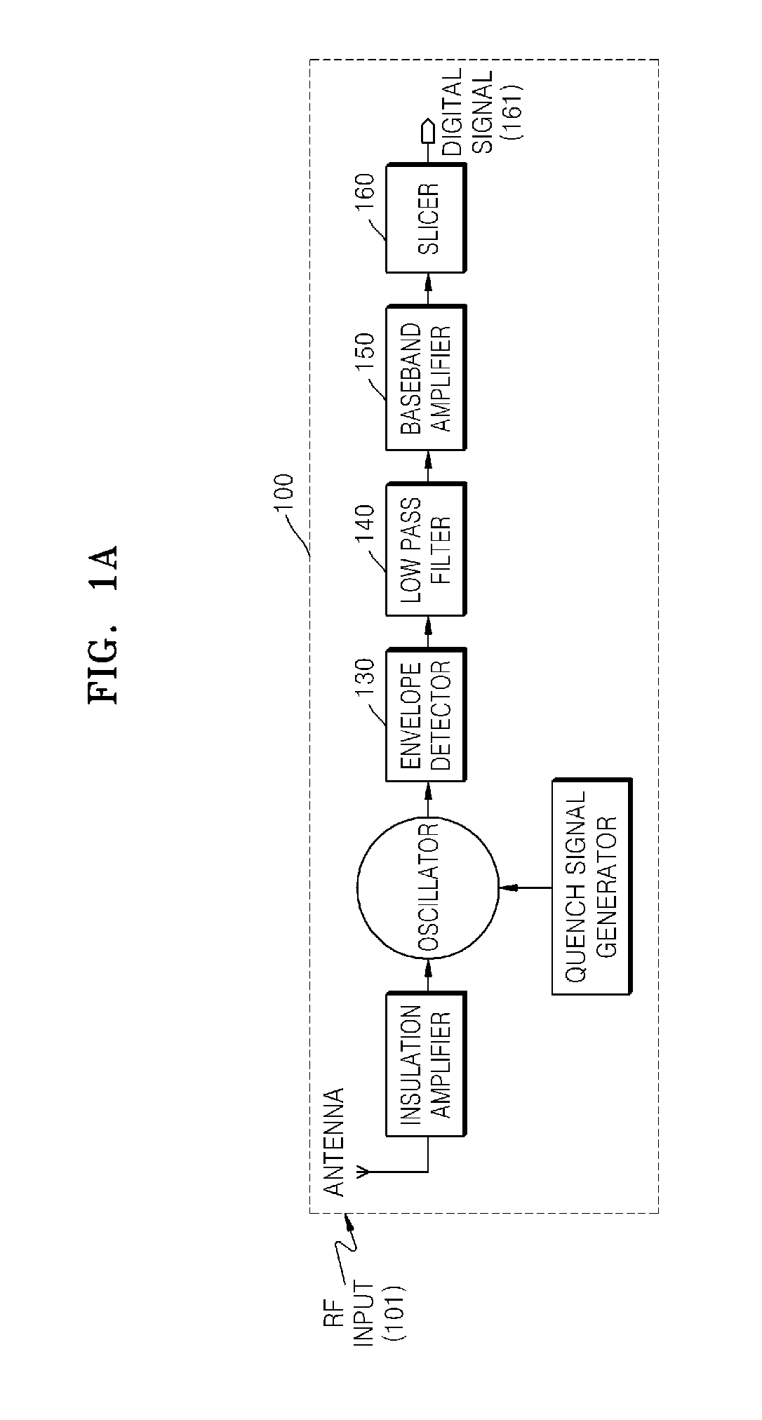
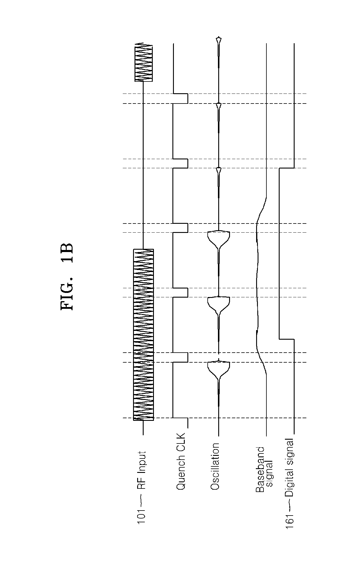
[0024]FIGS. 1A and 1B are, respectively, block and timing diagrams of a conventional super regenerative receiver 100. Referring to FIGS. 1A and 1B, the conventional super regenerative receiver 100 over-samples an input signal 101. In this case, a quench frequency is required to be much greater than an input signal data rate R. A cut-off frequency of a low pass filter 140 is much larger than the input signal data rate R and much smaller than the quench frequency in order to remove a quen...


PUM


Abstract

A low power super regenerative receiver and a method of reducing the power consumption of the low power super regenerative receiver are provided. The super regenerative receiver includes: an oscillator having a start-up time period starting oscillation that varies according to an existence of an input signal; and a power controller supplying power within the start-up time period of the oscillator.

Description

CROSS-REFERENCE TO RELATED PATENT APPLICATION[0001]This application claims the benefit of Korean Patent Application Nos. 10-2007-0129172, filed on Dec. 12, 2007, 10-2008-0111207, filed on Nov. 10, 2008, in the Korean Intellectual Property Office, the disclosure of which is incorporated herein in its entirety by reference.BACKGROUND OF THE INVENTION[0002]1. Field of the Invention[0003]The present invention relates to a super regenerative receiver, and more particularly, to a super regenerative receiver which reduces average power consumption by periodically turning on / off the power in correspondence with the power state of an oscillator which periodically turning on / off.[0004]The present invention is derived from a research project supported by the Information Technology (IT) Research & Development (R&D) program of the Ministry of Information and Communication (MIC) and the Institute for Information Technology Advancement (IITA) [2005-S-106-03, Development of Sensor Tag and Sensor No...

Claims


Application Information

Patent Timeline
Patent Type & Authority Applications(United States)
IPC IPC(8): H04B1/16
CPCH04B1/24Y02B60/50H04W52/0225Y02D30/70
Inventor KANG, HOYONGYU, XIAOHUAKIM, JI EUNNGUYEN, TRUNG KIENYOON, DAE YOUNGKIM, NAE SOOPYO, CHEOL SIGHAN, SEOK KYUNLEE, SANG GUG
Owner ELECTRONICS & TELECOMM RES INST
Why Eureka
Try Eureka