Stents with polymer-free coatings for delivering a therapeutic agent

a technology of stents and coatings, applied in the field of stents with polymer-free coatings for delivering a therapeutic agent, can solve the problems of coatings containing a coatings containing such a type of therapeutic agent without a polymer being generally ineffective in delivering the therapeutic agent, and presenting certain other limitations

Inactive Publication Date: 2009-06-18
BOSTON SCI SCIMED INC
View PDF8 Cites 69 Cited by
  • Summary
  • Abstract
  • Description
  • Claims
  • Application Information

AI Technical Summary

Problems solved by technology

Both of these types of coatings may have certain limitations.
Coatings containing a therapeutic agent without a polymer are generally ineffective in delivering the therapeutic agent since such coatings offer little or no control over the rate of release of the therapeutic agent.
Though the use of polymers in coatings can provide control over the rate of release of the therapeutic agent therefrom, the use of such polymers in coatings may present certain other limitations.
For example, the polymer in the coating may react adversely with the blood and cause thrombosis.
Moreover, some polymer coating compositions do not actually adhere to the surface of the medical device.
However, since the polymer does not adhere to the medical device, the coating composition is susceptible to deformation and damage during loading, deployment and implantation of the medical device.
Any damage to the polymer coating may alter the therapeutic agent release profile and can lead to an undesirable increase or decrease in the therapeutic agent release rate.
Also, surfaces coated with compositions comprising a polymer may be subject to undesired adhesion to other surfaces.
When the stent is expanded or uncrimped, the coating on the struts that have adhered to each other can be damaged, torn-off or otherwise removed.
Moreover, if the polymer coating is applied to the inner surface of the stent, it may stick or adhere to the balloon used to expand the stent when the balloon contacts the inner surface of the stent during expansion.
Such adherence to the balloon may prevent a successful deployment of the medical device.
Similar to balloon-expandable stents, polymer coatings on self-expanding stents can also interfere with the delivery of the stent.
Polymer coatings located on the outer or abluminal surface of the stent can adhere to the sheath as it is being pulled back and disrupt the delivery of the stent.

Method used


Image

  • Stents with polymer-free coatings for delivering a therapeutic agent
  • Stents with polymer-free coatings for delivering a therapeutic agent
  • Stents with polymer-free coatings for delivering a therapeutic agent

Examples


Embodiment Construction

5.1 The Medical Device

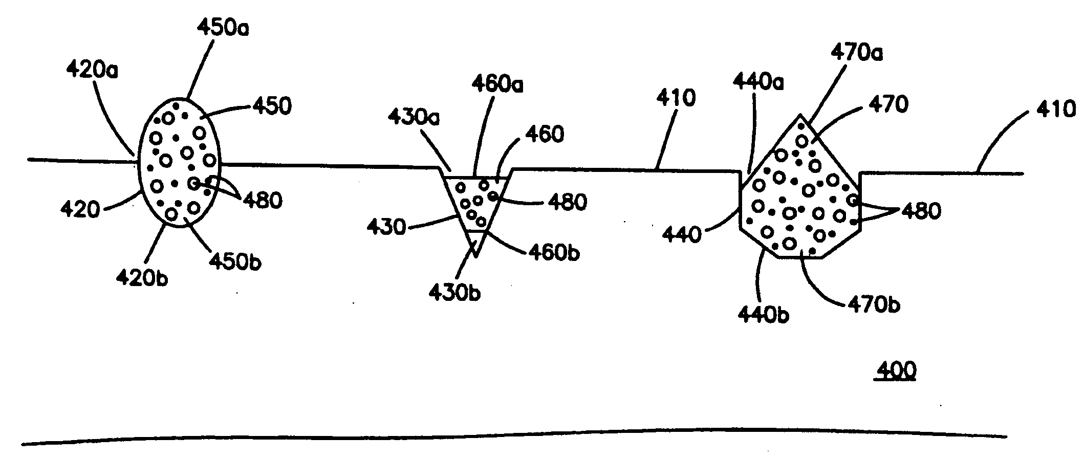
[0027]The medical devices described herein generally include a substrate having at least one surface. For instance, in the case where the medical device is an intravascular stent, the substrate is the stent sidewall structure and the surface is the abluminal surface of the stent. A cavity is disposed in the substrate and a pellet comprising a non-polymeric material having a plurality of pores therein is disposed in the cavity. A therapeutic agent is disposed in at least some of the pores for delivery to a patient.

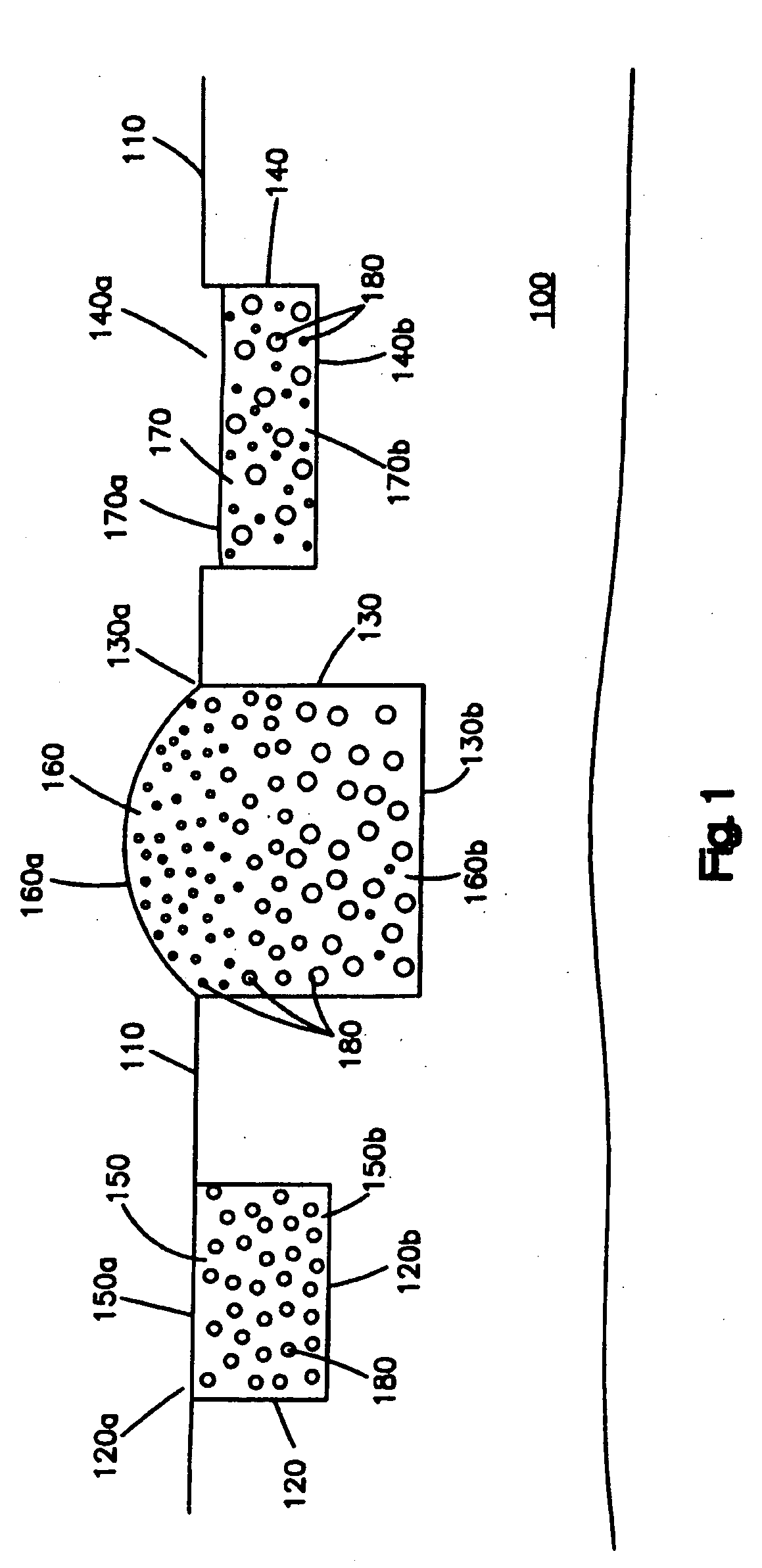
[0028]FIG. 1 shows one embodiment of the medical device, which can be a stent. The medical device comprises a substrate 100 having a surface 110. In this embodiment, the surface 110 is free of any coating, i.e., is not covered by a coating. In other embodiments, a coating may be disposed on at least a portion of the surface 110. As shown in the figure, there are three cavities 120, 130 and 140 disposed in the substrate 100. Each cavity comprises two op...


PUM


Abstract

Described herein are implantable medical devices, such as intravascular stents, for delivering therapeutic agents to a patient, and methods for making such medical devices. The medical devices comprise a substrate having at least a cavity therein and a pellet disposed in the cavity. The pellet comprises a non-polymeric material having a plurality of pores therein. A therapeutic agent is disposed in at least some of the pores.

Description

[0001]This application claims priority to U.S. Provisional Application No. 60 / 951,551 filed on Jul. 24, 2007, which is incorporated herein by reference in its entiretyINTRODUCTION[0002]Described herein are implantable medical devices, such as intravascular stents, for delivering therapeutic agents to a patient, and methods for making such medical devices. The medical devices comprise a substrate having at least a cavity therein and a pellet disposed in the cavity. The pellet comprises a non-polymeric material having a plurality of pores therein and a therapeutic agent disposed in at least some of the pores.2.0 BACKGROUND[0003]Medical devices have been used to deliver therapeutic agents locally to the body tissue of a patient. For example, stents having a coating containing a therapeutic agent, such as an anti-restenosis agent, have been used in treating or preventing restenosis. Currently, such medical device coatings include a therapeutic agent alone or a combination of a therapeut...

Claims


Application Information

Patent Timeline
Patent Type & Authority Applications(United States)
IPC IPC(8): A61F2/82
CPCA61F2/91A61F2/915A61F2002/91575A61F2250/0023A61F2250/0068A61F2230/0013A61L31/146A61L31/16A61L2300/416A61F2210/0076A61F2220/005A61L31/082
Inventor KOKATE, JAYDEEP Y.IFTEKHAR, M. ARIFWEBER, JAN
Owner BOSTON SCI SCIMED INC
Why Eureka
Try Eureka