Method and process to ensure that a vehicular travel path recording that includes positional errors can be used to determine a reliable and repeatable road user charge

Inactive Publication Date: 2009-06-18
SKYMETER
View PDF7 Cites 125 Cited by
  • Summary
  • Abstract
  • Description
  • Claims
  • Application Information

AI Technical Summary

Benefits of technology

[0072]The processor may be for thinning only 2×2 groups of cells

Problems solved by technology

Automotive congestion, whether of roads, streets, highways or parking spaces, is due to excessive demand for these facilities, and causes harm to the commercial and personal productivity of the businesses and people living in the area near and surrounding congested roads and areas.
Furthermore, automotive congestion is known to raise the risk of personal injury, death, or property damage due to crashes for those vehicles that are moving on congested facilities.
Moreover, fuel taxation does not distinguish between congested and uncongested roads and times, hence offering road authorities no ability to design pricing signals that could be used to control congestion.
For these requirements, a complete set of solutions is not currently available.
However, none of these work satisfactorily in harsh signal environments, in particular in the downtown “urban canyon” where they are most critically required.
Current position-determination systems such as Global Navigation Satellite System (GNSS) and any of a number of terrestrial systems, such as TV-GPS or cellular tower triangulation positioning systems (“positioning systems”), are subject to multipath errors that disturb and sometimes dominate signals when operating in harsh signal environments, such as are found in built-up cities (“urban canyon”).
Specifically, existing devices have one or more of the following problems.
They:1. do not work satisfactorily in steep terrain or built-up areas (“urban canyon”)2. do not provide an auditable evidentiary record such as is needed in non-refutable financial application (such as charging for road or parking use)3. are difficult to maintain because they require volatile data on board (such as m

Method used


Image

  • Method and process to ensure that a vehicular travel path recording that includes positional errors can be used to determine a reliable and repeatable road user charge
  • Method and process to ensure that a vehicular travel path recording that includes positional errors can be used to determine a reliable and repeatable road user charge
  • Method and process to ensure that a vehicular travel path recording that includes positional errors can be used to determine a reliable and repeatable road user charge

Examples


case 1

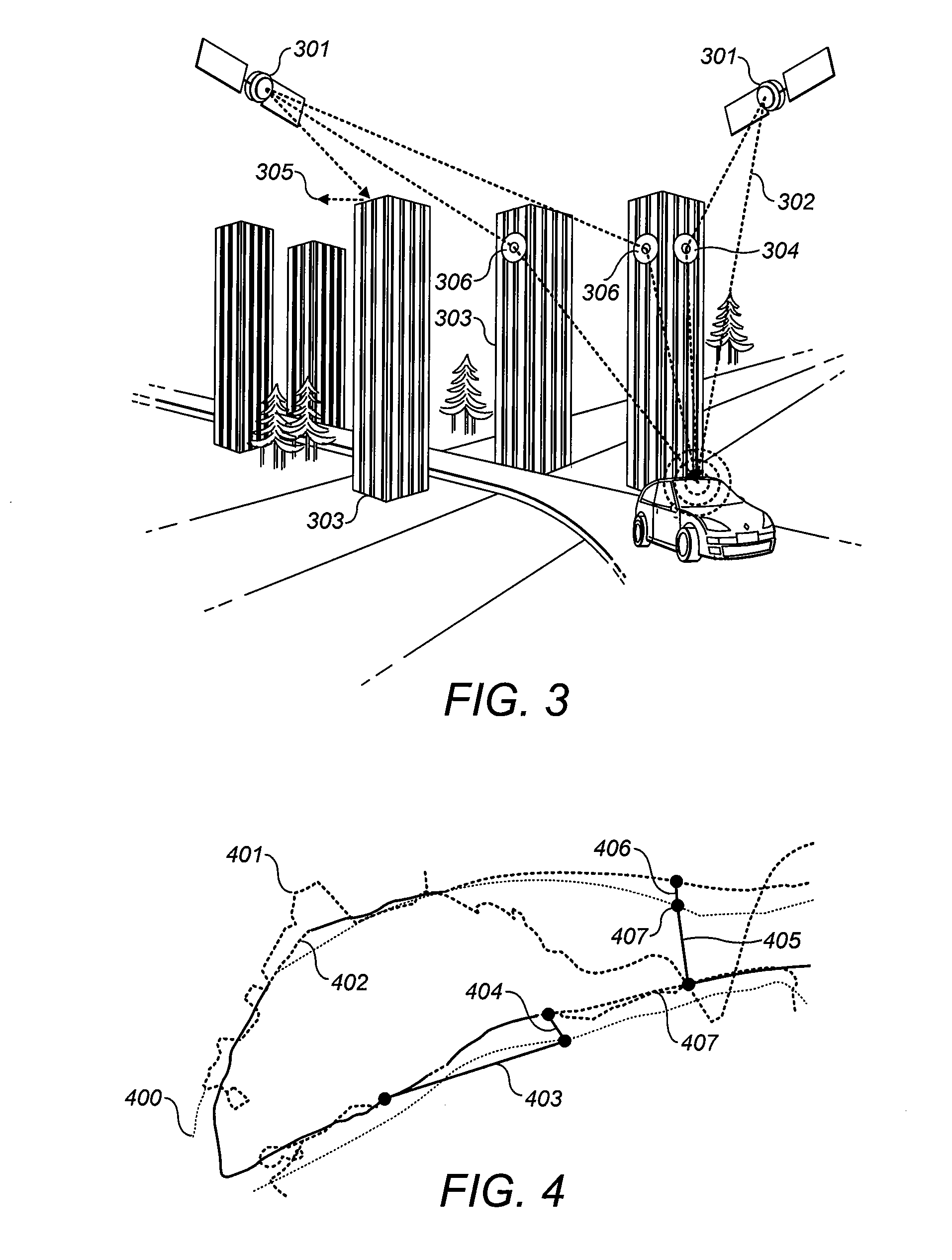
[0232]Case 1: Cells that have temporal overlaps (one of the cells is “touched” twice within a very short time span). In FIG. 6.2, the journey passed through cell B then A, then back through B. If the toll is a lump sum per cell (touch), then B would be charged twice. If the toll is related to duration in the zone, B would be overcharged. If related to distance within the cell (as intended by this invention), then B would be correctly charged. The tendency of multipath error to sometimes exaggerate distance traveled can be countered by using the Douglas-Peucker process to smooth the journey. (For example, a 2005 report by Siemens showed a 7.5% error in distance calculation in one built-up area; similar errors were common in a battery of 2006 tests executed by Transport for London in the UK). As an alternative, such a study for each municipality can derive a discount map related to the degree of local distance error, but this is not likely necessary.)

case 2

[0233]Case 2: A journey that hovers on the edge of two cells (FIG. 6.3). This is a degenerate instance of Case 1. This can be treated in as Case 1, but may be unfair if the pricing for cell A is very different than that in cell B. Rather, it would be seen as fairer if all of the duration and distance were assigned to the cell with the smaller charge.

[0234]In the instance of case 2, a high threshold setting might put both cells off the path (unfair to tolling authority) or a low threshold setting might put both cells on the path (unfair to the motorist). This can be handled by choosing the cell with the higher weight or by subsequent “path thinning”.

[0235]It is possible to distinguish Case 1 and Case 2 by noting that in Case 1 the duration for one cell is considerably less than that for the other 621, while in Case 2 the durations are nearly coincident 631. A method to distinguish these is trivial.

[0236]Since these cells are relatively small, it is not difficult to design the price m...

case 3

[0237]Case 3: As a more difficult case, FIG. 6.4 represents a trip that touched the same cells several times (such as “circling” for parking or lost in an urban context, or on a mountain switchback in a rural context). This is handled by summing all data in the same cell (location) that occurs within a time threshold. Theoretically this could happen in the OBU, but that may be too inflexible. Performed at the data center, this could be made flexible (e.g., a jurisdiction may wish to charge more for “circling” but not for the spatial circumstances of a switchback) and would be the first step and would compress Qj to the degree that a motorist was circling or otherwise driving around in a small area. Since a zonelog begins and ends with a parking episode, it is not possible for the cells to sum across trips (say on the two journeys to and from the store). Note that this step of data compression effectively loads a single cell with multiple touches and exaggerates the length of time th...


PUM


Abstract

The invention relates to a system and a method for addressing three problems:
  • (A) generate a tollpath of consistent length by determining one of a possible set of paths which are all the same length in cell-count every time the same journey is taken,
  • (B) determine a consistent price for each tollpath by setting pre-determined values on those cells such that every possible path variant of a specific journey produces the same toll, and
  • (C) determine the correct price for each tollpath by adjusting prices in each cell to account for the exact distance actually represented (some roads pass through a cell parallel to the cell edges and some pass through at an angle) so that the toll calculated exactly matches the toll that would be calculated had the exact linear, analogue distance been measured on the actual road.

Description

CROSS-REFERENCE TO RELATED APPLICATIONS[0001]This application is a continuation-in-part of co-pending U.S. patent application Ser. No. 11 / 688,977, filed Mar. 21, 2007, which claims benefit of U.S. provisional patent application Ser. No. 60 / 783,855, filed Mar. 21, 2006 and U.S. provisional patent application Ser. No. 60 / 858,728, filed Nov. 14, 2006, this application also claims benefit of U.S. provisional patent application Ser. No. 60 / 987,131, filed Nov. 12, 2007. Each of the aforementioned related patent applications is herein incorporated by reference.FIELD OF THE INVENTION[0002]The present invention lies in the field of Global Navigation Satellite System (GNSS) receivers and related applications.BACKGROUND OF THE INVENTION[0003]Automotive congestion, whether of roads, streets, highways or parking spaces, is due to excessive demand for these facilities, and causes harm to the commercial and personal productivity of the businesses and people living in the area near and surrounding ...

Claims


Application Information

Patent Timeline
IPC IPC(8): G01S1/00G06F17/00
CPCG01C21/28G01S19/14G01S19/22G07C5/008G06Q30/0283G07B15/02G07B15/063G01S19/42
Inventor GRUSH, BERNARD
Owner SKYMETER
Why Eureka
Try Eureka