Static electricity and dust removing apparatus

a technology of static electricity and dust removal apparatus, which is applied in the direction of carpet cleaners, cleaning machines, cleaning equipments, etc., can solve the problems of reducing the ion concentration of ions in the work environment, the inability to keep the dust removal dust-free, and so as to improve the quality of the processing of the matter to be processed and prevent the contamination of the work environment

Inactive Publication Date: 2009-06-25
KOGANEI
View PDF9 Cites 21 Cited by
  • Summary
  • Abstract
  • Description
  • Claims
  • Application Information

AI Technical Summary

Benefits of technology

[0019]Schemes of forming the airflow and actuating the air curtains and the ion spout nozzle in the box at a processing start time and at a processing completion time are set at a constant, so that, at a time of spraying the ionized air on the matters to be processed and after the processing completion of the matters to proceeded, an interior of the processing space becomes in a state where no dust is present. Therefore, quality of the processing performed to the matters to be processed is enhanced.
[0020]The removed dust in the processing space is prevented from being leaked to the outside, so that the work environment can be prevented from being contaminated due to the dust.

Problems solved by technology

In this case, the matters to be processed cannot be kept clean after dust removal.
Moreover, the removed dust may fly and float around the work environment, which results in contamination of the work environment.
However, when the ionized air is mixed into the main airflow flowing from the nozzle, an ion concentration therein is decreased and static electricity removing efficiency is decreased, whereby a long time is required to complete a static electricity and dust removing operation.
Meanwhile, if the open / close door is operated at a time of inserting the matters to be processed into the box, an operator has to frequently operate the open / close door for carrying in and carrying out the matters to be processed, whereby there is a problem of low operability in a processing operation.

Method used


Image

  • Static electricity and dust removing apparatus
  • Static electricity and dust removing apparatus
  • Static electricity and dust removing apparatus

Examples


Embodiment Construction

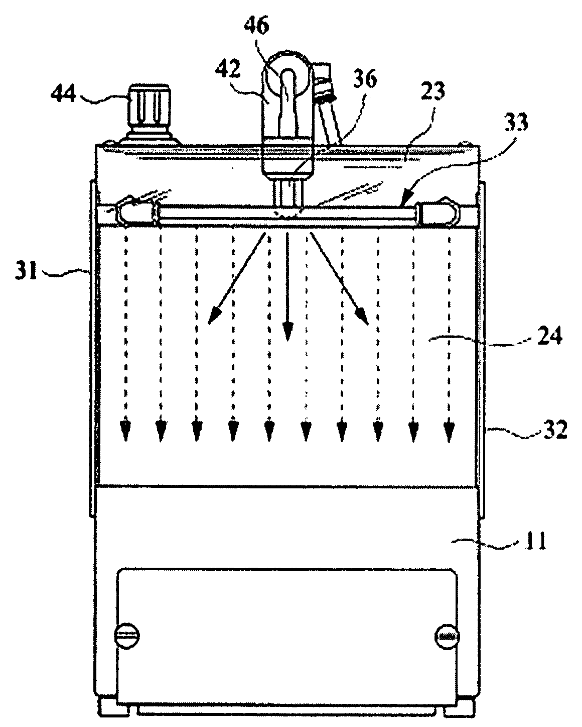
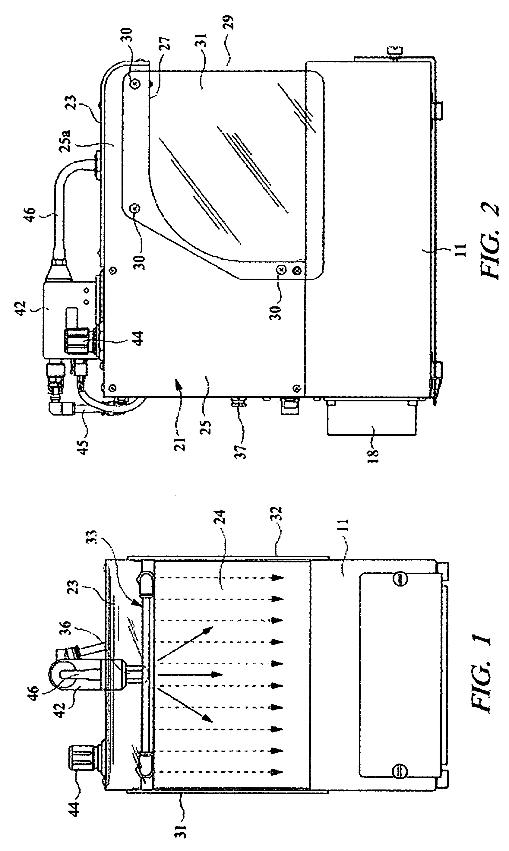
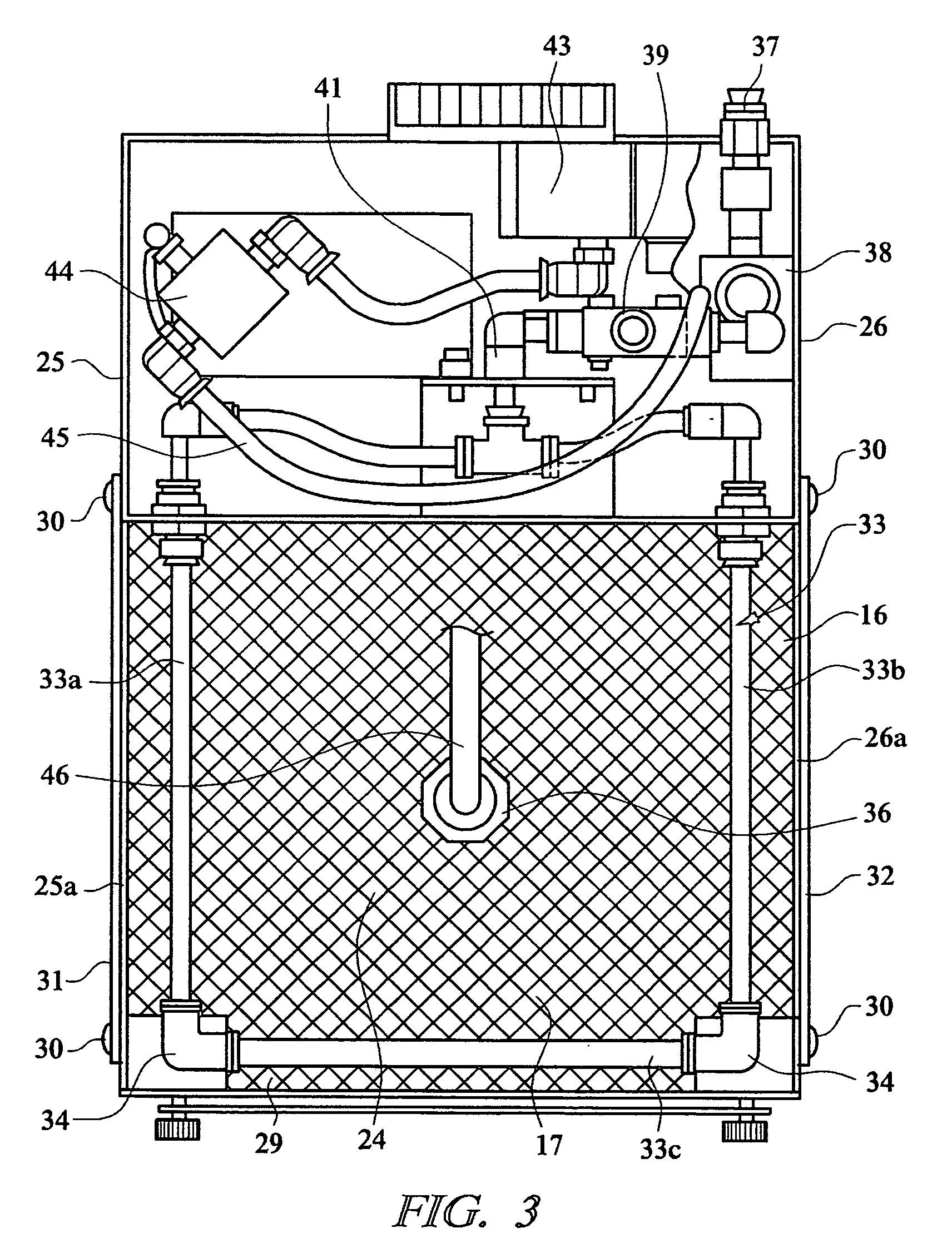
[0031]An embodiment of the present invention will be detailed below based on the drawings. This static electricity and dust removing apparatus has a base box 11 formed by combining plate materials. As shown in FIG. 4, in this base box 11, there is incorporated a blower, that is, an air blower 15 which has a motor 12, a fan 13 driven for rotation by the motor, and a case 14 accommodating these components. Inside the base box, a space for forming a flow of air, that is, an airflow path is formed. On a front end side of the base box 11, an airflow inlet port 16 is formed so that air vertically flows into the base box. An expanded metal 17 having many vents is attached to the airflow inlet port 16, whereby matters to be processed are prevented from entering from the airflow inlet port 16 into the base box 11. When the air blower 15 is driven, as shown by arrows in FIG. 4, air flows into the base box 11 from many vents of the expanded metal 17 provided to the airflow inlet port 16 and th...


PUM


Abstract

This static electricity and dust removing apparatus has a base box (11) provided with an airflow inlet port (16), and a processing head (23) attached to the base box (11) through a support column (21), wherein a processing space (24) is formed between the airflow inlet port (16) and the processing head (23). Air curtains for isolating the processing space (24) from the outside due to air from a spout of an air spout pipe (33) are formed at a front opening portion (29) and right and left side opening portions (28) of the apparatus. Ionized air generated by an ion generator (42) is spouted into the processing space (24), so that the ionized air is sprayed on matters to be processed which are disposed in the processing space (24) and dust is removed from the matters to be processed. Thereby, a static electricity and dust removing operation to the dust adhering to the matters to be processed can be efficiently performed within a short time, and work environment can be prevented from being contaminated due to a leakage of the removed dust.

Description

TECHNICAL FIELD[0001]The present invention relates to a static electricity and dust removing apparatus, which sprays ionized air on parts or the like of industrial products as matters to be processed to remove dust adhering to the matters to be processed and not to contaminate work environment.BACKGROUND ART[0002]In manufacturing parts of industrial products such as electrical components and in assembling the parts to manufacture the industrial products, dust including solid particles, foreign substances, and motes adhering to the parts has to be removed. Since the dust adhering to the parts includes dust adhering to them by static electricity, if ionized air is sprayed on the parts to remove the dust while neutralizing and removing the static electricity on surfaces of the parts, the dust can be reliably removed. As above, techniques, which remove the dust adhering to the parts or the like of the industrial products as workpieces, i.e., the matters to be processed while neutralizin...

Claims


Application Information

Patent Timeline
Patent Type & Authority Applications(United States)
IPC IPC(8): A47L13/40A47L5/00A47L9/02B08B5/02B08B6/00B08B15/02H05F3/04
CPCB08B5/02B08B6/00H05F3/04B08B15/023B08B2215/003B08B9/00
Inventor ISHIJIMA, TAKAHIROINOMATA, JUNOHKAWA, SHIGERU
Owner KOGANEI
Why Eureka
Try Eureka