
Prestressed Rolling Mill Housing Assembley With Improved Operational Features

Inactive Publication Date: 2009-06-25
I2S
View PDF8 Cites 12 Cited by
  • Summary
  • Abstract
  • Description
  • Claims
  • Application Information

AI Technical Summary

Benefits of technology

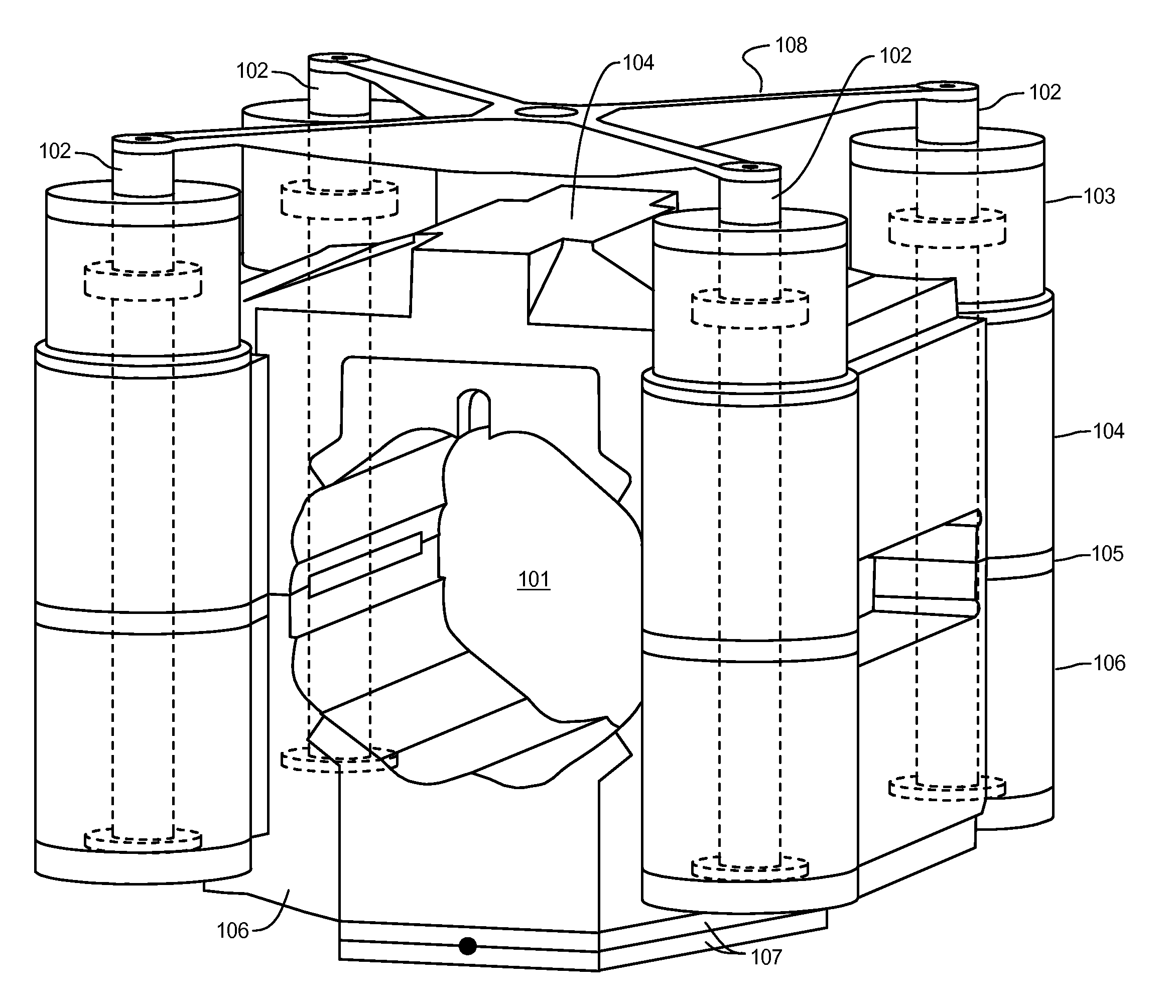
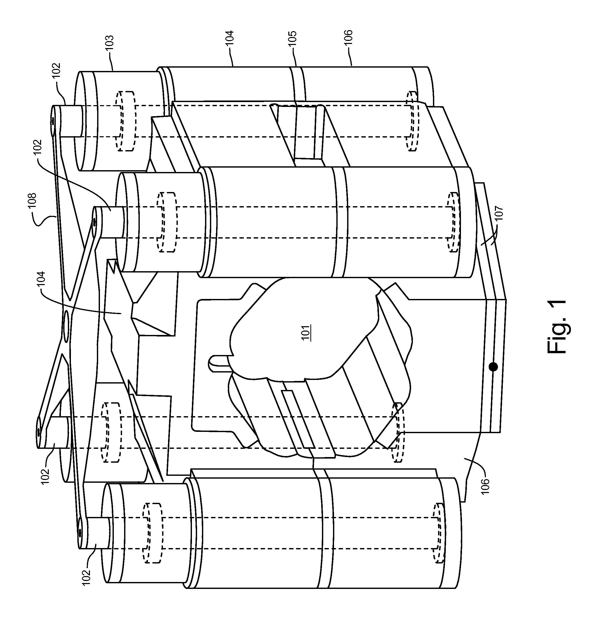
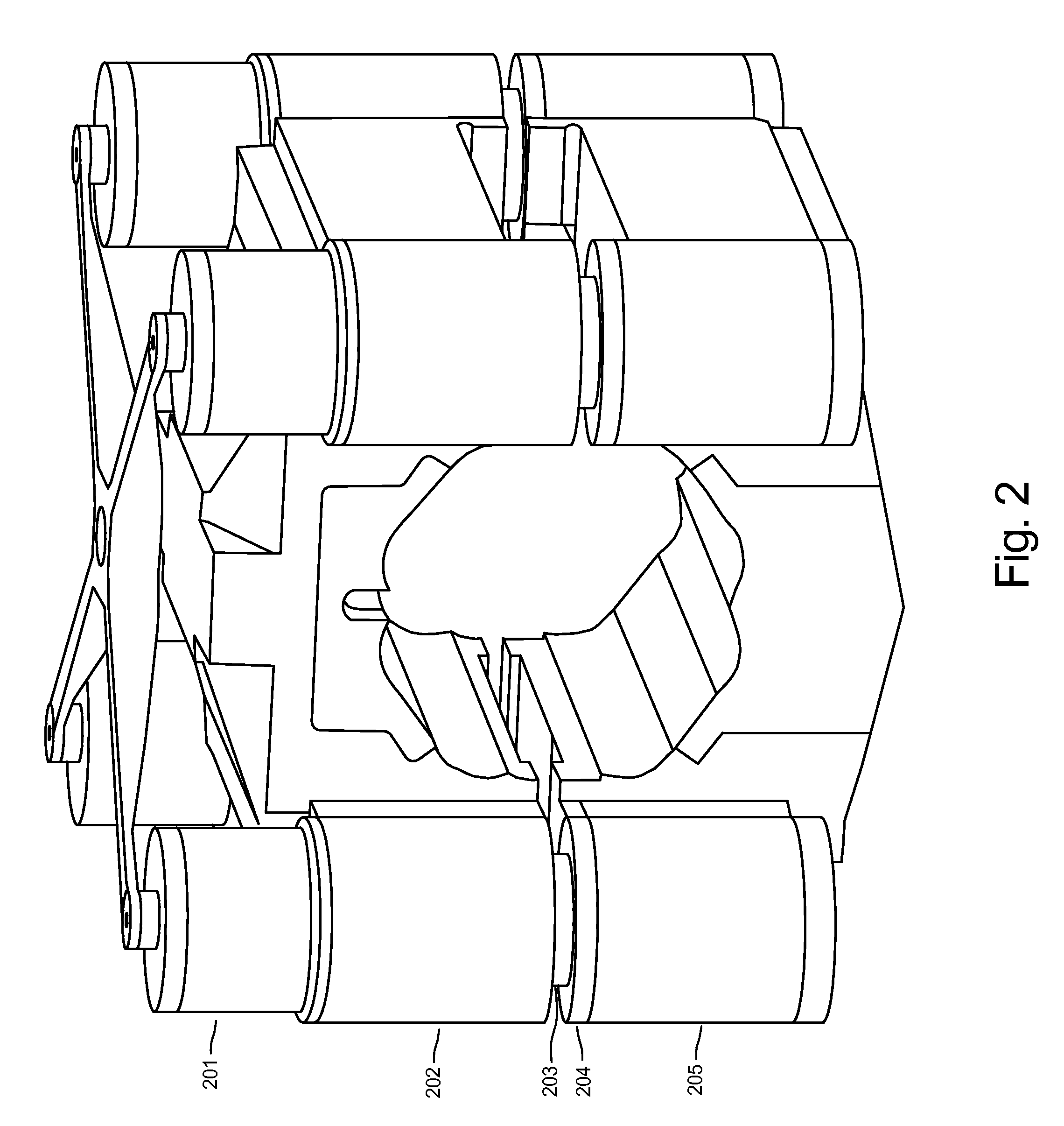
[0018]It is a primary object of the present invention to provide a pre-stressed rolling mill which has the advantages of a conventional mono-block mill housing, utilizing a Cluster mill gauge control system, and overcomes limitations and operational problems just described. It is highly desirable to have a rolling mill with a high apparent mill stiffness, a simplified gauge control system, a large work roll gap opening for threading, a rapid work roll gap opening method, a roll force measurement, satisfactory side to side tilting, and is able to use the work rolls over a much wider diameter range. Such a mill is capable of operating satisfactorily as a commercial temper mill and a commercial cold mill.

Problems solved by technology

One disadvantage to using a Cluster mill is a very small roll gap opening when there is a strip breakage.
Depending upon how quickly the entry side metal strip can be stopped, there may be damage to the rolls and ancillary equipment with a significant amount of metal strip to remove.
Sometimes, it is very difficult to remove the cluster mill rolls from the mono block due to jamming from broken strip.
In addition, the Cluster mill has a limited range of work roll diameters that will operate within the design of the mono block.
This lowers economic appeal.
Work rolls are normally surface refinished by regrinding when they are worn out, and a limiting operating range makes reuse by grinding very limited.
Another disadvantage of the Cluster mill is the reduced ability to be flexible for a varied rolling operation.
In contrast, the mono block Cluster mill is unattractive for a mill that is capable of both temper and cold rolling operations.
In particular, the small work roll diameter range is unsuitable for a mill configured to do both types of rolling.
The mono block design has a poor ability to thread the mill due to the small roll opening.
It is difficult for the beginning end of the strip to always be flat and suitably ready to conveniently enter a small roll gap.
The strip may be reluctant to enter the roll gap bite due to minor entry strip bending issues and require the manual intervention of an operator with long handled manual tools.
In a mono block design it is difficult to determine the rolling force, i.e. the vertical separation force, between the two work rolls during the rolling operation.
This highly restricts the ability to measure the rolling force with accuracy.
The mono block is not designed for a convenient and accurate tilting arrangement when there is a significant side to side gauge variance in the metal strip, that is, a wedge shaped strip.
Since the mono block does not have a rolling force measurement, it is difficult to make an accurate side to side rolling gap correction.
The rotation of the crown eccentric rings used for profile control do not provide enough tilting capability.
Consequently, a wedge shaped strip will have other problems in rolling which include strip breakage, creating camber, creating centerbuckle, creating uneven edge wave, and creating other unusual strip flatness problems.
The methods utilized are mechanically complicated, expensive to machine, and do not allow for the rapid roll opening needed to prevent damage when the strip breaks.
Also, the ability to adjust passline is very restricted and is equivalent to a mono block design.
The design is unsuitable for a high mill stiffness to take advantage of a simplified, satisfactory commercial gauge control system in a flat rolled product.
The methods utilized are mechanically complicated, expensive to machine, and do not allow for the rapid roll opening needed to prevent damage when the strip breaks.
The design does not take advantage of the mono block stiffness, but rather adds an additional pair of larger mill housings which greatly adds to the expense of the mill.
The design has a relatively low mill stiffness which requires a complicated gauge control system.

Method used


Image

  • Prestressed Rolling Mill Housing Assembley With Improved Operational Features
  • Prestressed Rolling Mill Housing Assembley With Improved Operational Features
  • Prestressed Rolling Mill Housing Assembley With Improved Operational Features

Examples


Embodiment Construction

[0025]The present invention utilizes the existing method of controlling the gauge at the exit of the cluster mill by rotating screwdown eccentric rings in the backing assemblies. This method is widely accepted commercially and is very preferable for commercial reasons. To that end, adding additional features and improvements preferably utilize a highly stiff mill to incorporate the existing gauge control method. U.S. Pat. No. 5,471,859 “Background Art” describes the use of eccentric rings or shafts on supporting roll bearings which are adjusted by a shaft and gearing system on either side of the rolling mill. The “Background Art” of U.S. Pat. No. 5,471,859 is incorporated by reference herein. The gauge control system where the exit gauge is substantially controlled by movement of at least one support roll bearing position by use of a rotating eccentric is herein called “eccentric bearing.”

[0026]For the purposes of this application, the side of the mill where the operator generally c...


PUM

PropertyMeasurementUnit
Fractionaaaaaaaaaa
Fractionaaaaaaaaaa
Timeaaaaaaaaaa

Abstract

The present invention provides a Cluster mill which utilizes a Cluster mill gauge control system, has a high mill stiffness, a large work roll gap for threading, a rapid work roll gap opening, accurate roll force computation, side to side tilting, and utilizes work rolls over a much wider diameter range.

Description

CROSS REFERENCE TO RELATED APPLICATIONS[0001]Not Applicable.STATEMENT REGARDING FEDERALLY SPONSORED RESEARCH OR DEVELOPMENT[0002]Not applicable.REFERENCE TO SEQUENCE LISTING, A TABLE, OR COMPUTER PROGRAM LISTING[0003]Not applicable.BACKGROUND OF THE INVENTION[0004](1) Field of the Invention[0005]This application is directed to improvements in rolling mill housings used in rolling operations in the flat rolled metal industry. In particular, the present invention is directed toward a multi-roll cluster type of rolling mill.[0006](2) Description of Related Art[0007]Cluster mills are popular in the rolling mill industry when a high gauge reduction is taken, a thin exit gauge is rolled, or a combination of the two. A cluster mill provides many advantages to the operation of a rolling mill and includes the following: small diameter work rolls, high housing stiffness, and a simplified gauge control. In many previous applications, the cluster mill housing has been built based on a mono bloc...

Claims


Application Information

Patent Timeline
IPC IPC(8): B21B29/00
CPCB21B13/147B21B31/028B21B31/04B21B2271/02B21B31/32B21B37/64B21B38/00B21B31/26
Inventor GUO, REMN-MIN
Owner I2S
Learn More