Exhaust pipe structure

a technology of exhaust pipe and structure, which is applied in the direction of mechanical equipment, machines/engines, transportation and packaging, etc., can solve the problems of reducing the durability and reliability affecting the service life etc., to reduce the vibration of the exhaust pipe, and suppress undesirable noise and vibration in the vehicle interior

Inactive Publication Date: 2009-06-25
TOYOTA JIDOSHA KK
View PDF0 Cites 5 Cited by
  • Summary
  • Abstract
  • Description
  • Claims
  • Application Information

AI Technical Summary

Benefits of technology

[0018]The third exhaust pipe is supported by the other support member at the part furthest from the phantom line, which connects the one support member and the second universal joint, the one support member supporting the part of the third exhaust pipe further from the second universal joint. This minimizes turning motion of the third exhaust pipe about the phantom line, although the third exhaust pipe tends to vibrate intensively due to its location at a free end on the downstream side of exhaust gas flow. This reduces vibrations of the exhaust pipe when the vehicle travels off-road or over an uneven road surface, while suppressing undesirable noise and vibrations in the vehicle interior.

Problems solved by technology

A load caused by these vibrations is thus imposed on the exhaust pipe, which disadvantageously lowers durability and reliability of the exhaust pipe.
In addition, the vibrations are transmitted through a support member for the exhaust pipe to a vehicle body, causing undesirable noise and vibrations in the vehicle interior.
This can cause the exhaust pipe to be displaced from its normal position in the static state.
When the vehicle travels off-road or over an uneven road surface, the exhaust pipe, supported at the position out of the normal mounting position, can be excessively displaced beyond the allowance range.
Thus, the exhaust pipe tends to interfere with peripheral components.
Nonetheless, supporting the exhaust pipe in this preferred manner is sometimes difficult mainly due to insufficient body strength at the position adjacent to the universal joint.
This could result in difficulty in supporting the exhaust pipe at its normal position in the static state.

Method used


Image

  • Exhaust pipe structure
  • Exhaust pipe structure
  • Exhaust pipe structure

Examples


first embodiment

[0027]An exhaust pipe structure according to the present invention will be described below with reference to FIGS. 1 to 4.

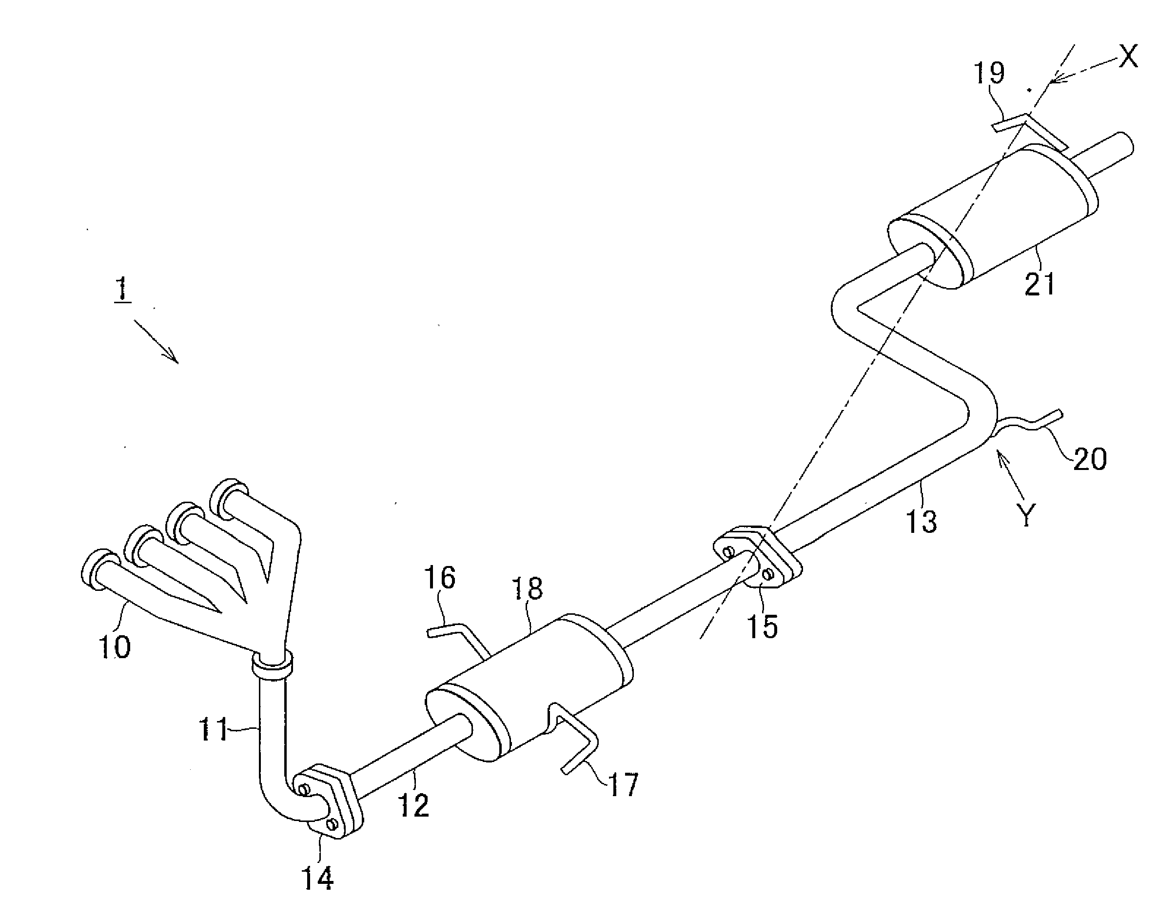
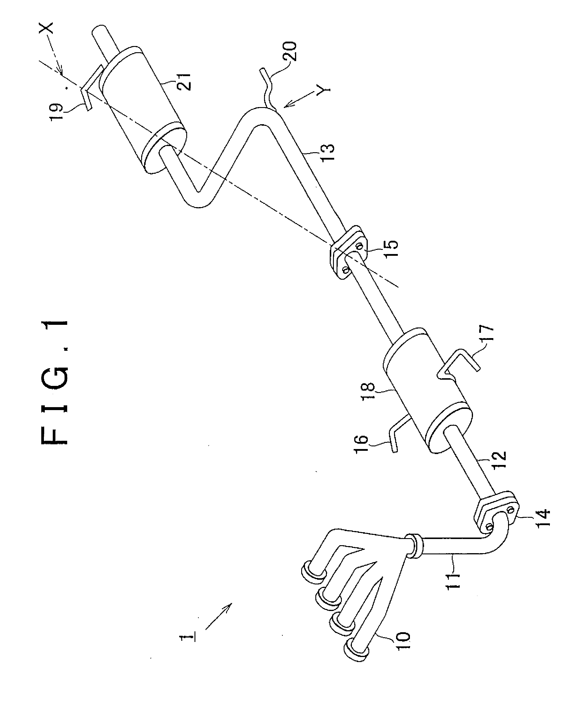
[0028]FIG. 1 is a perspective view of an exhaust pipe structure 1 according to the first embodiment of the invention. The exhaust pipe structure 1 includes: a first exhaust pipe 11 connected to an exhaust manifold 10 of the internal combustion engine; a second exhaust pipe 12 connected to the first exhaust pipe 11; and a third exhaust pipe 13 connected to the second exhaust pipe 12. The exhaust pipes 11, 12, 13 are provided in the lower portion of the vehicle body, where the internal combustion engine is mounted, in order of the first exhaust pipe 11, the second exhaust pipe 12, and the third exhaust pipe 13 from the front to the rear of the vehicle body. Exhaust gas from the internal combustion engine is discharged from the exhaust manifold 10 through the first exhaust pipe 11, the second exhaust pipe 12, and the third exhaust pipe 13 to the atmosphere.

[0029]The...

second embodiment

[0044]FIG. 5 is a schematic diagram of an exhaust pipe structure 2 when viewed from above the vehicle body 50. The center of gravity G3 of the second exhaust pipe 12 is located towards the rear of the vehicle body 50 with respect to the axis J1, which connects the support members 16 and 17, in other words, on the side of the ball joint 15. Thus, the weight of the second exhaust pipe 12 creates a moment that turns the exhaust pipe 12 about the axis J1 in the direction of the arrow R1. Accordingly, the load F1 is applied to the ball joint 15 in a direction that presses the ball joint 15 down (vertically downward from the sheet surface of FIG. 5, namely away from the vehicle body).

[0045]In turn, the center of gravity G4 of the third exhaust pipe 13 is located on the rearward side of the vehicle body 50, in other words, on the side opposite to the ball joint 15, with respect to the axis J2 connecting the support members 19 and 20. Thus, the weight of the third exhaust pipe 13 creates a...


PUM


Abstract

A center of gravity (G1) of a second exhaust pipe (12) is located on the side of an axis (J1) connecting two associated support members (16, 17) that is distal to a ball joint (15). Thus, creating a moment that applies a load (F1) to a ball joint (15 that presses the ball joint (15) up toward the vehicle body. In turn, by locating a center of gravity (G2) of a third exhaust pipe (13) on the side of an axis (J2) connecting two associated support members (19, 20) that is proximal to the ball joint (15) the weight of the third exhaust pipe (13) creates a moment which that applies a load (F2) to the ball joint (15) that presses the ball joint (15) down away from the vehicle body. Consequently, the load (F1) and the load (F2) of approximately the same magnitude act in opposite directions.

Description

BACKGROUND OF THE INVENTION[0001]1. Field of the Invention[0002]The present invention relates to a structure of an exhaust pipe connected to an internal combustion engine.[0003]2. Description of the Related Art[0004]Generally, vibrations generated by the internal combustion engine in operation are transmitted to the exhaust pipe connected to the internal combustion engine. A load caused by these vibrations is thus imposed on the exhaust pipe, which disadvantageously lowers durability and reliability of the exhaust pipe. In addition, the vibrations are transmitted through a support member for the exhaust pipe to a vehicle body, causing undesirable noise and vibrations in the vehicle interior. Therefore, in order to suppress transmission of exhaust pipe vibrations or absorb the vibrations, a widely used exhaust pipe structure has: an exhaust pipe including plural separate exhaust pipes connecting in series to join an exhaust manifold of the internal combustion engine; and a universal ...

Claims


Application Information

Patent Timeline
Patent Type & Authority Applications(United States)
IPC IPC(8): F16L9/22F01N13/08F01N13/18
CPCB60K13/04F01N13/0097F01N13/1805F01N13/08F01N13/18
Inventor YAMAGUCHI, JUNICHIHORIE, YOSHIKI
Owner TOYOTA JIDOSHA KK
Why Eureka
Try Eureka