
Ac Voltage Output Apparatus and Hybrid Vehicle Including the Same

a voltage output and hybrid technology, applied in the direction of dc-ac conversion without reversal, process and machine control, instruments, etc., can solve the problems of motors not being able to secure one or both voltages, affecting the operation of the motor, so as to suppress the distortion of the waveform of the ac voltage caused by abrupt load variation and periodic disturbance

Active Publication Date: 2009-06-25
TOYOTA JIDOSHA KK
View PDF10 Cites 28 Cited by
  • Summary
  • Abstract
  • Description
  • Claims
  • Application Information

AI Technical Summary

Benefits of technology

[0010]Another object of the present invention is to provide a highly stable AC voltage output apparatus.
[0042]Further, the repetitive control unit effectively suppresses disturbance periodically generated by the influence of inverter dead time. Further, as the load current compensating unit is additionally provided, distortion of AC voltage caused by abrupt load variation can be suppressed.

Problems solved by technology

In the electric motor drive and power processing apparatus disclosed in Japanese Patent Laying-Open No. 04-295202, however, it is impossible to generate the AC voltage across neutral points NA and NB while the three-phase AC motors MA and MB are driven.
Therefore, there might be a situation that the inverter driving the motor cannot secure one of or both of the voltages for driving the motors and for generating the AC voltage.
Further, in switching control of an inverter, generally, there is a dead time provided for preventing simultaneous turn-on of upper and lower arms, and this dead time causes waveform distortion in the waveform of AC voltage generated across the neutral points.
Particularly in a large power inverter such as used for a hybrid vehicle, the dead time is often set longer, resulting in more serious waveform distortion in the AC voltage generated across the neutral points.

Method used


Image

  • Ac Voltage Output Apparatus and Hybrid Vehicle Including the Same
  • Ac Voltage Output Apparatus and Hybrid Vehicle Including the Same
  • Ac Voltage Output Apparatus and Hybrid Vehicle Including the Same

Examples


first embodiment

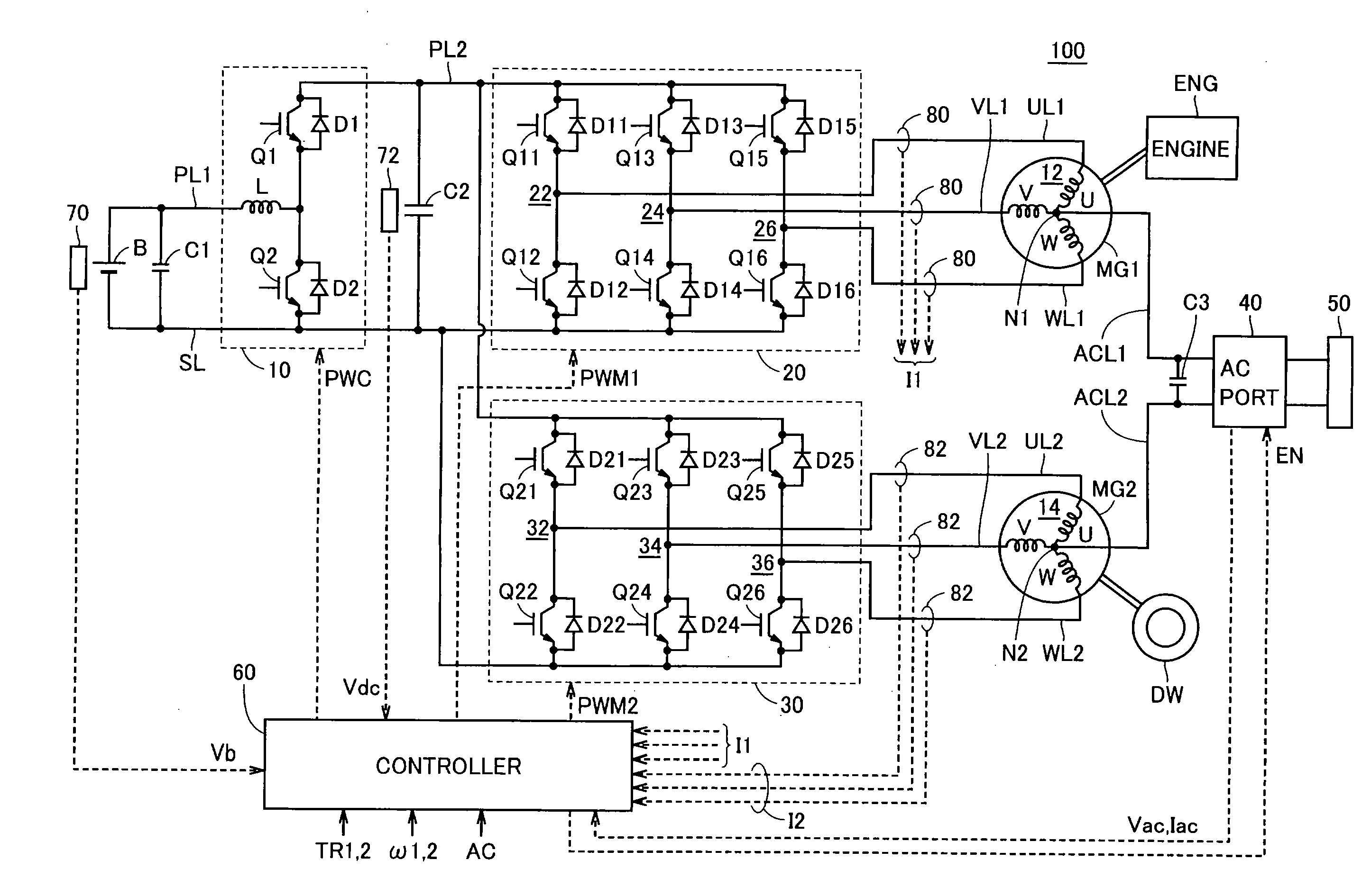
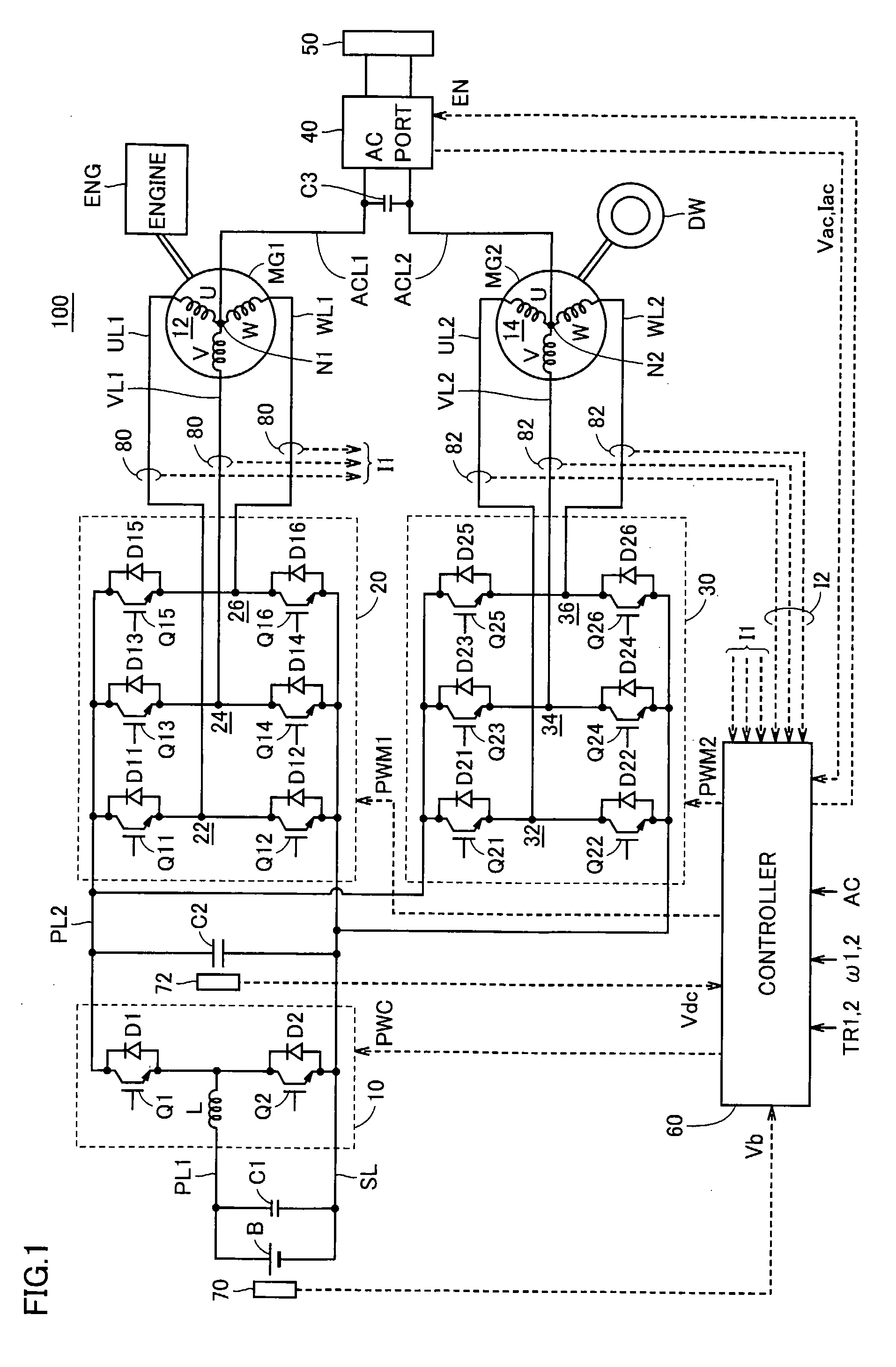
[0056]FIG. 1 is an overall block diagram of an AC voltage output apparatus 100 in accordance with the first embodiment of the present invention. Referring to FIG. 1, AC voltage output apparatus 100 includes an electric storage B, a boost converter 10, inverters 20 and 30, motor generators MG1 and MG2, a controller 60, capacitors C1 and C2, power lines PL1 and PL2, a ground line SL, U-phase lines UL1 and UL2, V-phase lines VL1 and VL2, W-phase lines WL1 and WL2, voltage sensors 70 and 72, and current sensors 80 and 82. AC voltage output apparatus 100 further includes AC output lines ACL1 and ACL2, a capacitor C3, an AC port 40 and a connector 50.

[0057]AC voltage output apparatus 100 is mounted on a vehicle, such as a hybrid vehicle having an engine ENG and a motor generator MG2 as power sources. Motor generator MG1 is incorporated in the hybrid vehicle, coupled to engine ENG and operating as a motor that can start the operation of engine ENG and as a generator driven by the engine EN...

second embodiment

[0120]In the first embodiment, the AC voltage reference value Vacr of sinusoidal wave is generated at multiplication unit 140 and feedback control is performed based on the deviation between the generated reference value Vacr and the voltage Vac detected at AC port 40, as shown in FIG. 4. Though the feedback control is common, high follow-up capability is required, as the voltage Vac must be adjusted to the reference value Vacr that varies at the commercial power source frequency ω. As a result, high-response control becomes necessary, while stable control may become difficult. Further, in order to realize high response, high speed operation is necessary. In view of the above, feedback control putting weight on stability is developed in the second embodiment.

[0121]The overall configuration of the AC voltage output apparatus in accordance with the second embodiment is the same as that of AC voltage output apparatus 100 in accordance with the first embodiment shown in FIG. 1.

[0122]FIG...

third embodiment

[0131]In the third embodiment, in addition to the approach of the second embodiment, feedback control based on the instantaneous value of voltage Vac is performed, and amount of compensation thereof is input to the first inverter control unit. Thus, subtle deviation that cannot be removed by the feedback control based on the average value of voltage Vac can be eliminated.

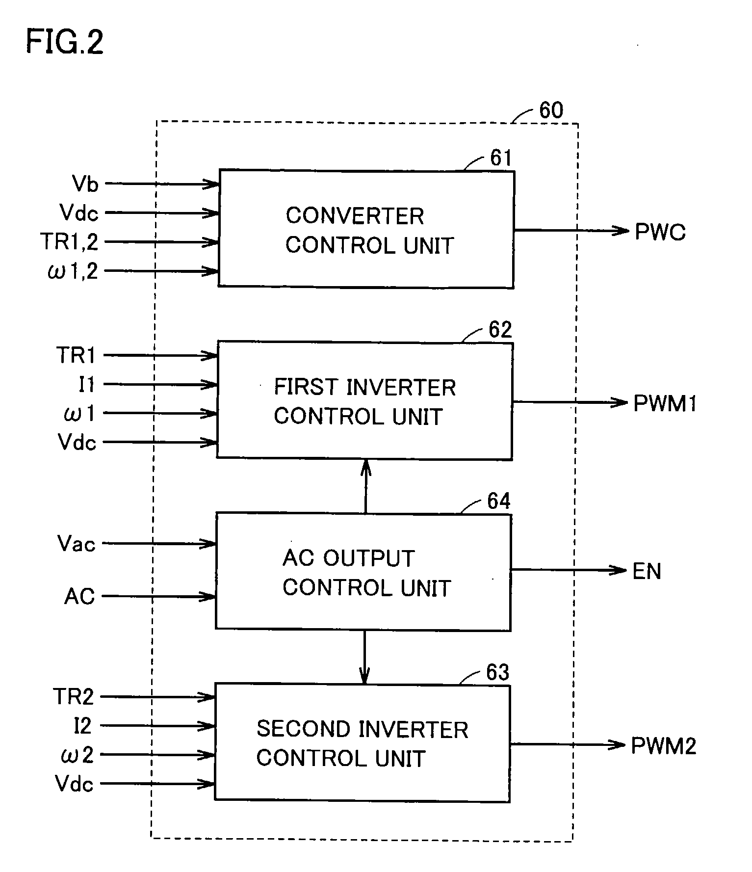
[0132]The overall configuration of AC voltage output apparatus in accordance with the third embodiment is the same as that of AC voltage output apparatus 100 of the first embodiment shown in FIG. 1. Further, the configurations of the converter control unit and of first and second inverter control units in accordance with the third embodiment are the same as those of converter control unit 61 and the first and second inverter control units 62 and 63 of the first embodiment shown in FIGS. 2 to 4.

[0133]FIG. 8 is a detailed functional block diagram of the first inverter control unit 62 and AC output control unit 64B in ...


PUM


Abstract

An AC command voltage obtained by compensating a reference value of a commercial AC voltage output from a multiplication unit using an FB control unit is multiplied by k (0≦k≦1) by a multiplication unit and output to a first inverter control unit, and the remaining part is output to a second inverter control unit. The first and second inverter control units generate signals, based on command voltages obtained by superposing the AC command voltage from an AC output control unit on respective phase command voltages.

Description

TECHNICAL FIELD[0001]The present invention relates to an AC (Alternating Current) voltage output apparatus and a hybrid vehicle including the apparatus. More specifically, the present invention relates to an AC voltage generating apparatus capable of generating an AC voltage as a commercial power source and outputting the generated voltage to a load, as well as to a hybrid vehicle provided with the apparatus.BACKGROUND ART[0002]Conventionally, attempts have been made to use a hybrid vehicle as a power supply system, for more effective use of hybrid vehicles. As an example, a hybrid vehicle having a dedicated inverter for converting a DC (Direct Current) voltage generated in the hybrid vehicle to a commercial AC voltage has been known.[0003]Meanwhile Japanese Patent Laying-Open No. 04-295202 discloses an electric motor drive and power processing apparatus capable of generating an AC voltage and supplying the voltage to an external apparatus without necessitating a dedicated inverter....

Claims


Application Information

Patent Timeline
Patent Type & Authority Applications(United States)
IPC IPC(8): B60K6/22H02P27/04G06F17/00B60L9/18B60L50/13B60L50/15H02M7/48H02P5/74
CPCB60L11/123B60L2210/20H02M7/48Y02T10/725H02M2001/009Y02T10/6217Y02T10/7077H02M2001/008B60L50/61H02M1/008H02M1/009Y02T10/62Y02T10/70Y02T10/72Y02T10/7072
Inventor OYOBE, HICHIROSAINAKAMURA, MAKOTOISHIKAWA, TETSUHIROTOGASHI, SHIGENORI
Owner TOYOTA JIDOSHA KK
Learn More