Plasma display panel and front panel thereof

a technology of display panel and plasma, which is applied in the direction of electric discharge tubes, gas-filled discharge tubes, electrical apparatus, etc., can solve the problems of achieve the effects of increasing the resolution of screens, increasing display lines, and increasing the speed of addressing

Inactive Publication Date: 2009-06-25
FUJITSU HITACHI PLASMA DISPLAY LTD
View PDF1 Cites 5 Cited by
  • Summary
  • Abstract
  • Description
  • Claims
  • Application Information

AI Technical Summary

Benefits of technology

[0007]Increasing the speed of addressing is an issue related to the driving of a plasma display panel. If faster addressing is possible, more display lines can be scanned than is possible during present addressing periods, making it possible to increase the resolution of screens. Moreover, rather than increasing the display lines, increasing the sustain period by the amount by which the required time is shortened through faster addressing makes it possible to increase the number of display discharges and thus increase the luminosity.

Problems solved by technology

Increasing the speed of addressing is an issue related to the driving of a plasma display panel.

Method used


Image

  • Plasma display panel and front panel thereof
  • Plasma display panel and front panel thereof
  • Plasma display panel and front panel thereof

Examples


Embodiment Construction

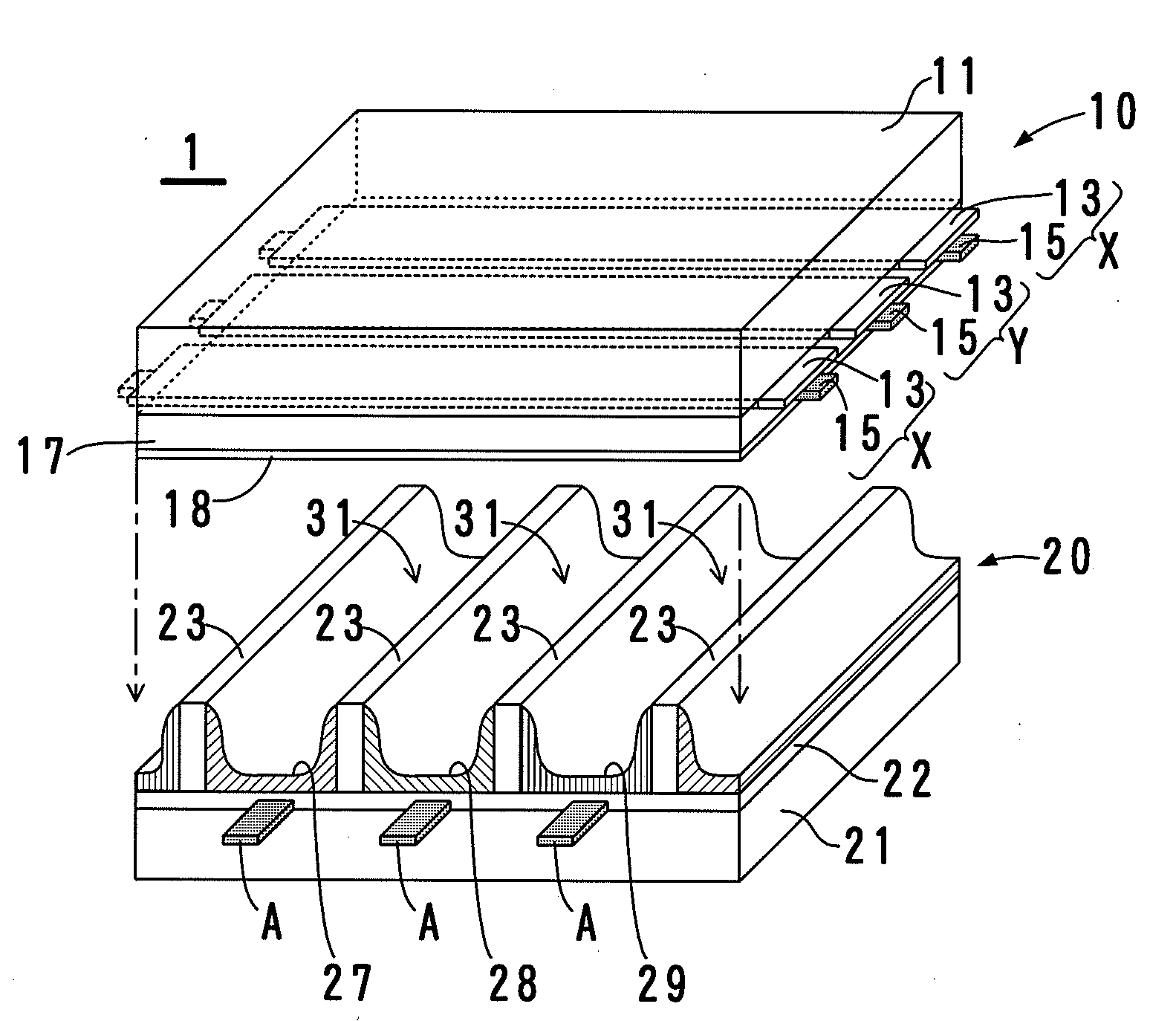
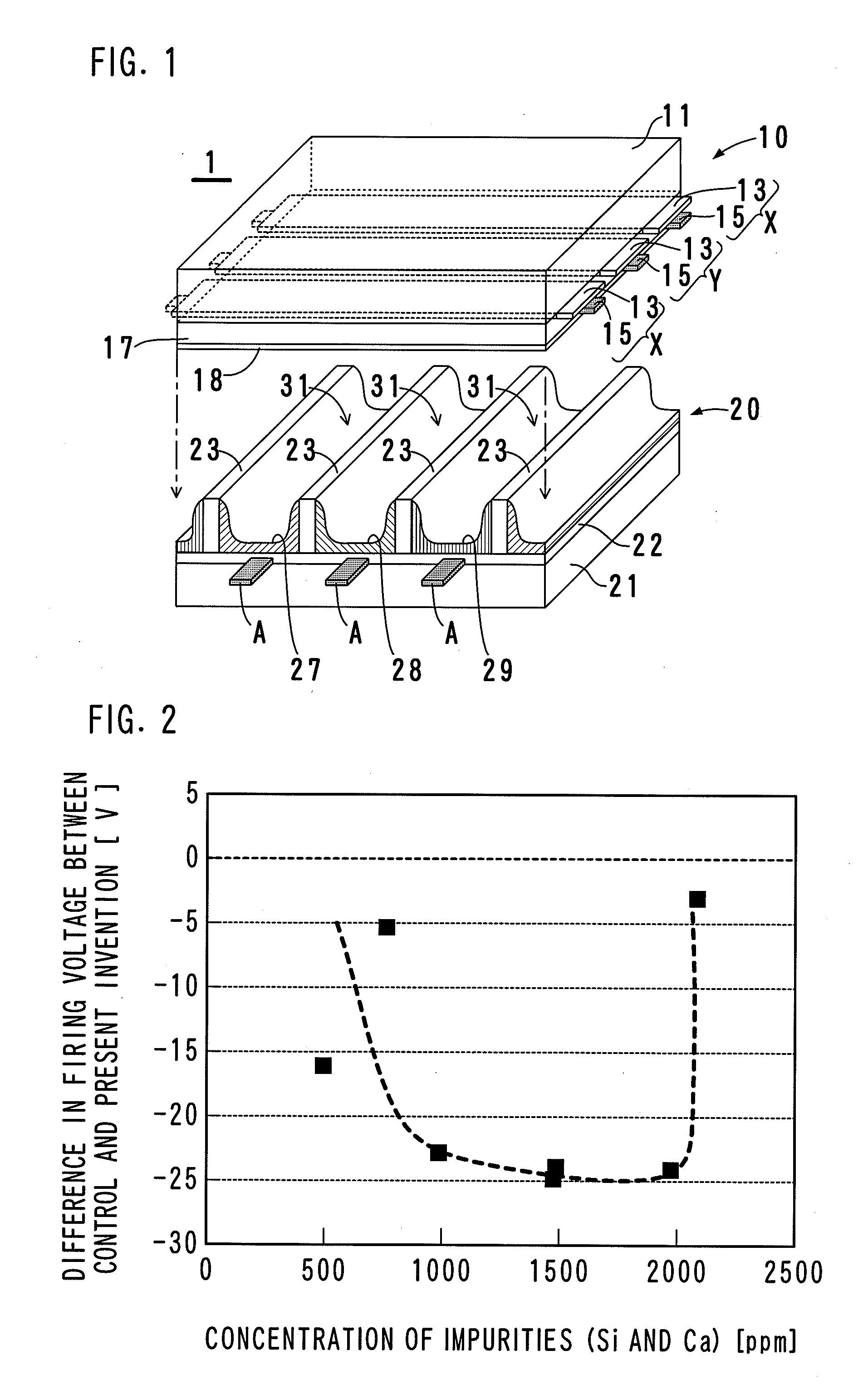
[0016]The present invention can be applied in various types of plasma display panels that include a magnesium oxide film for discharge. A plasma display panel 1, shown in FIG. 1, is one example thereof.

[0017]The plasma display panel 1 includes a front panel 10 and a back panel 20. In order to facilitate understanding of the internal structure, the front panel 10 and the back panel 20 are illustrated as being separate from each other in FIG. 1; however, in reality, the two panels make contact with each other. The front panel 10 includes: a glass substrate 11; display electrodes X, which are first electrodes; display electrodes Y, which are second electrodes; a dielectric layer 17 for AC driving; and a magnesium oxide film 18, serving as a protective layer that prevents sputtering from occurring on the dielectric layer 17. The rear panel 20 includes: a glass substrate 21; address electrodes A, which are third electrodes; a dielectric layer 22; multiple partitions 23; a red (R) fluores...


PUM

PropertyMeasurementUnit
thickaaaaaaaaaa
thickaaaaaaaaaa
thickaaaaaaaaaa

Abstract

A plasma display panel includes a magnesium oxide film (18) that covers electrodes (X, Y) and is exposed to a discharge gas space (31). The magnesium oxide film (18) includes silicon and calcium as impurities, and the content of the impurities in the magnesium oxide film (18) is 800 to 2050 ppm by weight. By suppressing the total content of silicon and calcium in the film to 800 to 2050 ppm by weight, the discharge start voltage can be reduced by no less than 20 volts.

Description

TECHNICAL FIELD[0001]The present invention relates to a plasma display panel having a magnesium oxide film that covers electrodes, and particularly relates to improvements in magnesium oxide films.BACKGROUND ART[0002]AC-type plasma display panels include an insulator that covers electrodes. The insulator is composed of a dielectric layer approximately 10 to 50 μm thick and a protective film approximately 0.5 to 1 μm thick that is laminated onto the dielectric layer. The dielectric layer is a layer for building a sufficient wall charge. The protective layer is made of a material with advanced anti-sputtering properties, and prevents the deterioration of the dielectric layer due to ion collisions occurring during discharge.[0003]The protective layer is typically made of magnesium oxide (MgO, or magnesia). Because magnesium oxide is a high γ matter, a protective layer made of magnesium oxide has a property of easily emitting secondary electrons. Due to the emission of secondary electro...

Claims


Application Information

Patent Timeline
Patent Type & Authority Applications(United States)
IPC IPC(8): H01J17/49H01J11/12H01J11/40
CPCH01J11/40H01J11/12
Inventor WADA, MASAYUKIYOSHINO, FUMIAKIKAWASAKI, TATSUHIKO
Owner FUJITSU HITACHI PLASMA DISPLAY LTD
Why Eureka
Try Eureka