Touch panel and display device using the same

a technology of carbon nanotubes and touch panels, applied in the field of touch panels, can solve the problems of uneven resistance over an entire area of the touch panel, poor mechanical durability of the ito line, and relatively complicated methods

Active Publication Date: 2009-06-25
TSINGHUA UNIV +1
View PDF99 Cites 69 Cited by
  • Summary
  • Abstract
  • Description
  • Claims
  • Application Information

AI Technical Summary

Problems solved by technology

In use, due to an electrical field of the user, coupling capacitances between the user's fingers and the sensing nodes disturb coupling capacitances between the first conductive lines and the second conductive lines.
The sensing lines and the driving lines (e.g., ITO lines) are generally formed by means of ion-beam sputtering, and this method is relatively complicated.
Furthermore, the ITO lines have generally poor mechanical durability, low chemical endurance, and uneven resistance over an entire area of the touch panel.
Additionally, the ITO layers have relatively low transparency.
All the above-mentioned problems of the ITO layers tend to yield a touch panel with somewhat low sensitivity, accuracy, and brightness.

Method used


Image

  • Touch panel and display device using the same
  • Touch panel and display device using the same
  • Touch panel and display device using the same

Examples


Embodiment Construction

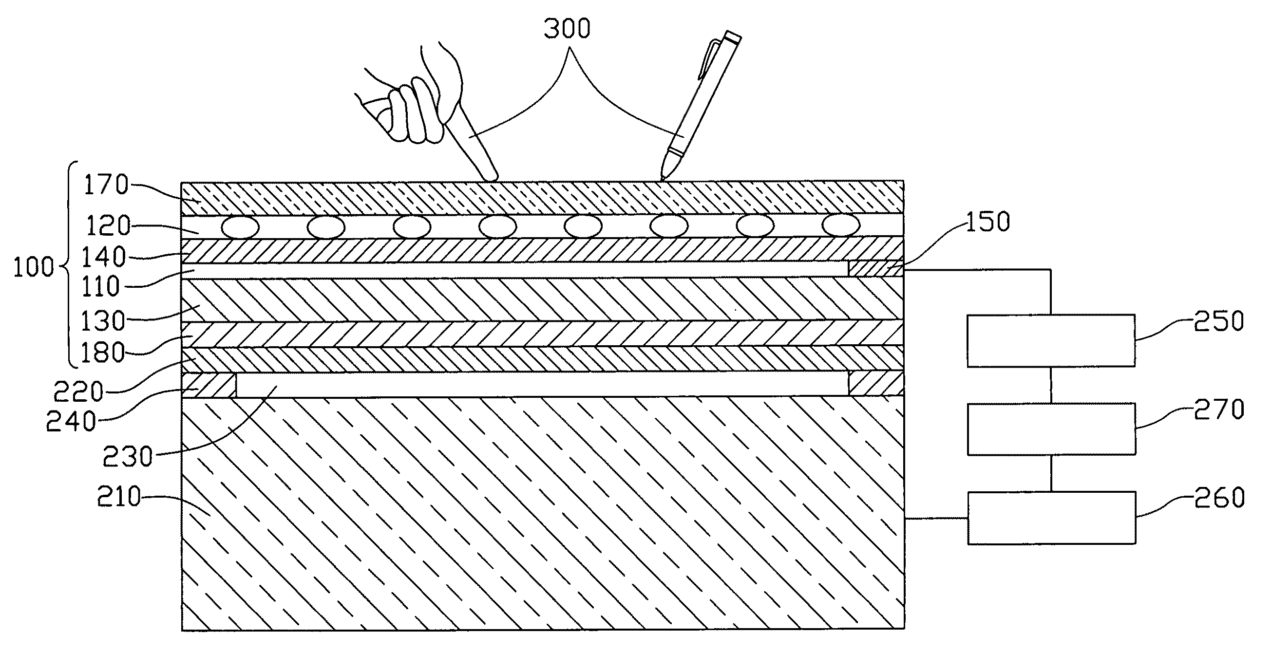
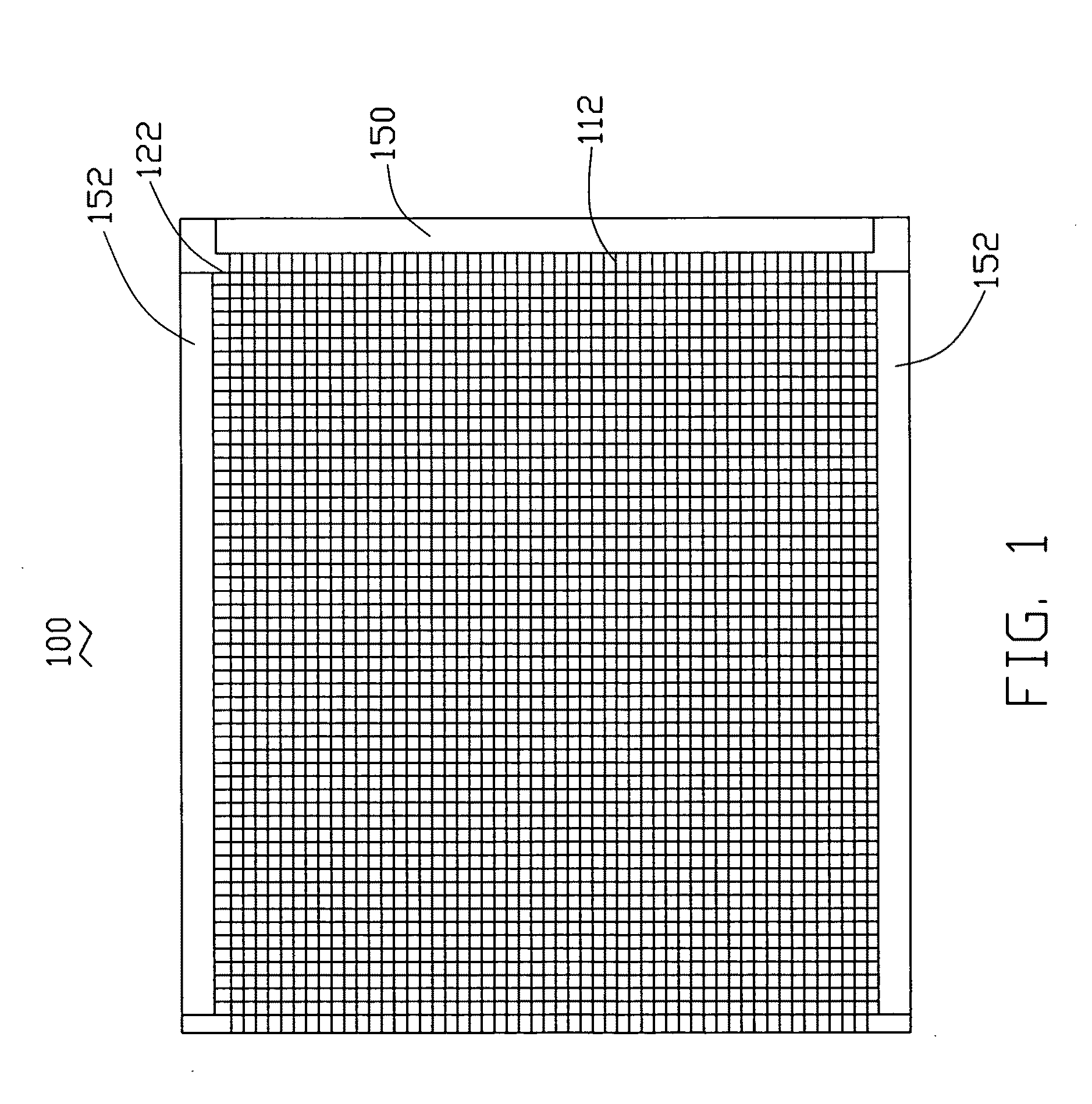
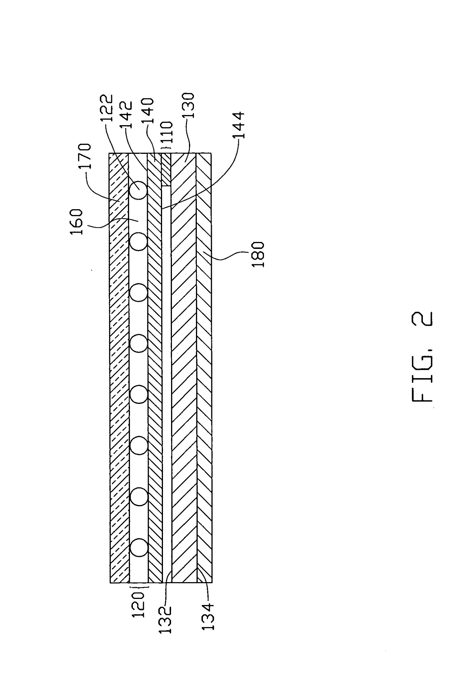
[0023]Reference will now be made to the drawings to describe, in detail, embodiments of the present touch panel and display device using the same.

[0024]Referring to FIG. 1 and FIG. 2, a touch panel 100 includes a first conductive layer 110, a second conductive layer 120 spaced apart from and opposite to the first conductive layer 110, and a capacitive sensing member 150. The first conductive layer 110 includes a plurality of first conductive lines 112. The second conductive layer 120 includes a plurality of second conductive lines 122. The first conductive lines 112 and the second conductive lines 122 are disposed in two separate planes and where the second conductive lines 122 pass over the first conductive lines 112 they are considered to be spatially intersecting with each other. The plurality of first conductive lines 112 are connected to the capacitive sensing member 150.

[0025]The touch panel 100 can further includes a first substrate 130 and a second substrate 140. The first s...


PUM


Abstract

A touch panel includes a first conductive layer, a second conductive layer and a capacitive sensing member. The first conductive layer includes a plurality of first conductive lines. The second conductive layer separated from the first conductive layer includes a plurality of second conductive lines. One of the plurality of conductive lines is located above the other plurality of conductive lines. The capacitive sensing member is connected to the first conductive lines. At least one of the first and second pluralities of conductive lines includes carbon nanotube wires. The carbon nanotube wires each include a plurality of carbon nanotubes. Further, a display device using the above-described touch panel is also included.

Description

RELATED APPLICATIONS[0001]This application is related to commonly-assigned applications entitled, “TOUCH PANEL”, filed ______ (Atty. Docket No. US17449); “TOUCH PANEL”, filed ______ (Atty. Docket No. US17448); “TOUCH PANEL AND DISPLAY DEVICE USING THE SAME”, filed ______ (Atty. Docket No. US17889); “TOUCH PANEL AND DISPLAY DEVICE USING THE SAME”, filed ______ (Atty. Docket No. US17861); “TOUCH PANEL AND DISPLAY DEVICE USING THE SAME”, filed ______ (Atty. Docket No. US17820); “ELECTRONIC ELEMENT HAVING CARBON NANOTUBES”, filed ______ (Atty. Docket No. US18066); “TOUCH PANEL AND DISPLAY DEVICE USING THE SAME”, filed ______ (Atty. Docket No. US17862); “TOUCH PANEL AND DISPLAY DEVICE USING THE SAME”, filed ______ (Atty. Docket No. US17818); “TOUCH PANEL AND DISPLAY DEVICE USING THE SAME”, filed ______ (Atty. Docket No. US18263); “TOUCHABLE CONTROL DEVICE”, filed ______ (Atty. Docket No. US18262); “TOUCH PANEL AND DISPLAY DEVICE USING THE SAME”, filed ______ (Atty. Docket No. US17888); “...

Claims


Application Information

Patent Timeline
Patent Type & Authority Applications(United States)
IPC IPC(8): G06F3/041
CPCG06F3/044Y10T428/268G06F2203/04107G06F3/0446
Inventor JIANG, KAI-LILIU, LIANGFAN, SHOU-SHAN
Owner TSINGHUA UNIV
Why Eureka
Try Eureka