Camera flash module and method for controlling same

a technology of flash module and flash module, which is applied in the direction of exposure control, color signal processing circuit, instruments, etc., can solve the problem of not being able to easily control the amount of light to produce a consistent amount, and achieve the effect of reducing the flash intensity

Active Publication Date: 2009-06-25
NOKIA TECHNOLOGLES OY
View PDF9 Cites 84 Cited by
  • Summary
  • Abstract
  • Description
  • Claims
  • Application Information

AI Technical Summary

Benefits of technology

[0016]According to various embodiment of the present invention, the camera settings, including the exposure time and the predetermined intensity of the flash, for the capturing of the first test image and the second test image, are computed. In particular the average luminance of one or more preview images are used to determined the predetermined intensity of flash such that average luminance of the second test image is within a predetermined range, so as to prevent the second test image from being underexposed or overexposed.
[0017]Ac...

Problems solved by technology

While camera flashes, such as xenon flashes, can provide a high intensity light source to illumina...

Method used


Image

  • Camera flash module and method for controlling same
  • Camera flash module and method for controlling same
  • Camera flash module and method for controlling same

Examples


Embodiment Construction

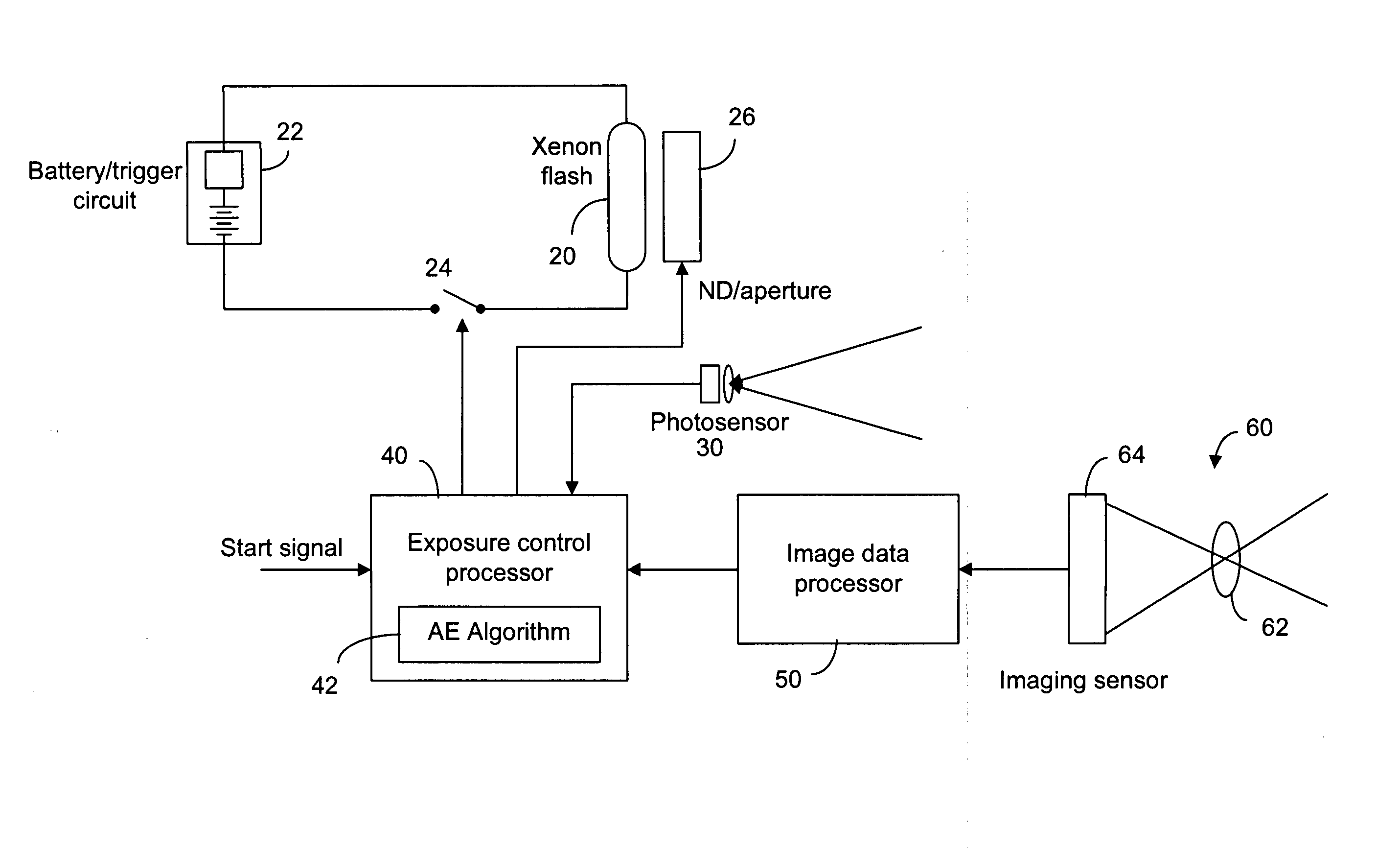
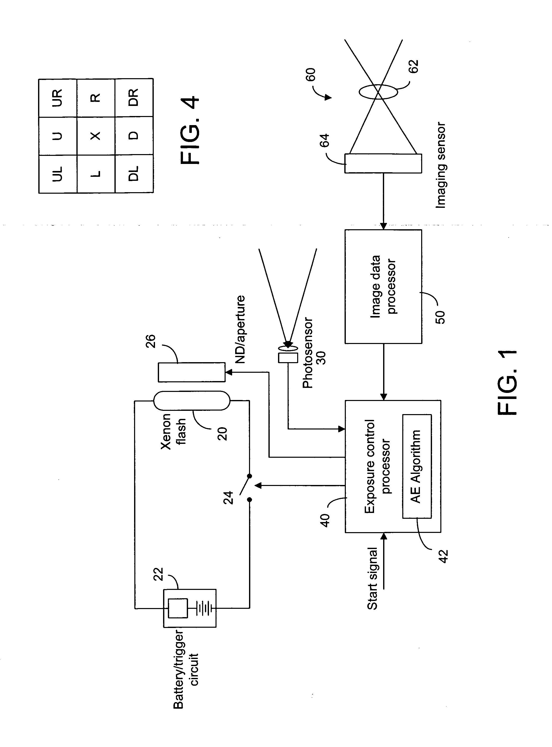
[0035]The present invention is concerned with controlling the amount of light provided by a camera flash when taking pictures. As shown in FIG. 1, the camera flash 20 is powered by a power source 22 and triggered by a trigger pulse provided by a trigger control 24. A flash intensity attenuator or reducer, such as a mechanical iris or a neutral density (ND) filter 26 can be placed in front of the camera flash 20 to reduce the flash intensity. An exposure control module 40 having a software program 42 embedded in a computer readable storage medium to implement a flash intensity control algorithm based on the ambient light, the nature of the scene and the photographic mode, for example. A photosensor 30 can be used to detect the scene brightness with or without flash light, for example. In addition, image data from the camera 60 is used in the auto-exposure calculation. Typically, the camera 60 has an imaging sensor 64 and one or more lenses 62 to form an image on the imaging sensor 64...


PUM


Abstract

An auto-exposure algorithm for controlling a camera flash uses image processing to identify important areas of the image affected by the flash, while disregarding highly reflective/illuminated areas and uses a ND filter to linearize the flash triggering with highly reflective scenes. The camera flash is controlled by the auto-exposure algorithm in two stages:
a pre-flash stage followed by a main-flash stage. In the pre-flash stage, two images are captured under the same camera settings regarding the exposure time, gain, iris and resolution. One image is captured with flash and one without. From the difference between the two images, a reference pixel is used to determine the flash intensity in the main-flash stage.

Description

[0001]This application claims priority and benefits to U.S. Patent Application Ser. No. 61 / 016,244, filed Dec. 21, 2007.FIELD OF THE INVENTION[0002]The present invention relates generally to a camera flash module and, particularly, to a camera flash module controlled by an auto-exposure algorithm.BACKGROUND OF THE INVENTION[0003]When taking pictures under inadequate ambient light, such as in total darkness or in low light, a camera flash is commonly used. Also, a camera flash can be used for fill-in purposes even when the ambient light is not low. While camera flashes, such as xenon flashes, can provide a high intensity light source to illuminate a scene to a great distance, they cannot be easily controlled to produce a consistent amount of light. It is known that the amount of light produced by a xenon flash can be increased or decreased by controlling the width of the trigger pulse. When the pulse width is short, the flash intensity can vary significantly. Thus, it is advantageous...

Claims


Application Information

Patent Timeline
IPC IPC(8): H04N17/00H04N5/222
CPCH04N5/2354H04N23/74G03B7/16G03B15/05G03B7/097H04N23/56H04N23/75
Inventor TREVELYAN, PHILIPIVANOV, ANGELKIRILOV, EMILVASILEV, IVAN
Owner NOKIA TECHNOLOGLES OY
Why Eureka
Try Eureka