
Image pickup apparatus, color noise reduction method, and color noise reduction program

a pickup apparatus and pickup method technology, applied in the field of image pickup apparatus, color noise reduction method, color noise reduction program, can solve the problems of image noise in the image becoming more of a problem, s/n ratio, degraded, etc., and achieve the effect of reducing color noise, noise reduction, and color noise reduction

Inactive Publication Date: 2009-06-25
SONY CORP
View PDF11 Cites 57 Cited by
  • Summary
  • Abstract
  • Description
  • Claims
  • Application Information

AI Technical Summary

Benefits of technology

[0016]By using this method, color noise can be removed before a normal demosaic process (an original demosaic process) is performed. Accordingly, this method is significantly effective for improving the quality of an image. However, in this method, a simplified demosaic process and a process for changing a luminance signal and a color difference signal subjected to a color noise reduction process to signals in a raw state are additionally performed, as compared in the case of normal camera signal processing.
[0017]That is, this method is particularly useful for high-performance image pickup apparatuses having sufficient resources, such as the features, performance, and capacity of hardware. However, a demand for appropriately and rapidly reducing color noise even in image pickup apparatuses having fewer resources is increasing.
[0019]Accordingly, the present invention provides an image pickup apparatus, a method, and a program for rapidly and effectively reducing color noise in an image signal including color signals of a plurality of colors without using a large amount of resources.
[0022]In the demosaic processing means, the generation unit performs computation using a target color signal (e.g., an R (red) signal or a B (blue) signal) representing an image signal to be processed and a predetermined different color signal (e.g., a G (green) signal) so as to generate a color-related signal (e.g., a color difference signal or a color ratio signal). Subsequently, the noise reduction unit performs a noise reduction process on the color-related signal generated by the generation unit. In this way, the demosaic processing is performed using a color-related signal having a reduced color noise.
[0023]Thus, noise reduction processing can be performed on a color-related signal generated through the demosaic processing. Accordingly, additional hardware is not necessary except for the noise reduction unit, and therefore, color noise can be reduced at high speed. In addition, since color noise can be reduced through the demosaic processing, color noise can be reduced most effectively.
[0024]As described above, according to the embodiment, a color noise component can be rapidly and most effectively reduced from an image signal including a plurality of color signals. That is, color noise can be effectively reduced.

Problems solved by technology

Accordingly, the S / N ratio (a signal to noise ratio) has been degraded, and therefore, noise in an image has become more of a problem.
As a result, an edge portion may be displayed with a false color, and the quality of the image may be significantly deteriorated.
If the characteristic of the noise signal is changed, it is difficult to separate a noise signal component from a picture signal component.
Accordingly, it is difficult to completely remove the color noise.

Method used


Image

  • Image pickup apparatus, color noise reduction method, and color noise reduction program
  • Image pickup apparatus, color noise reduction method, and color noise reduction program
  • Image pickup apparatus, color noise reduction method, and color noise reduction program

Examples


first exemplary embodiment

Exemplary Configuration of Image Pickup Apparatus

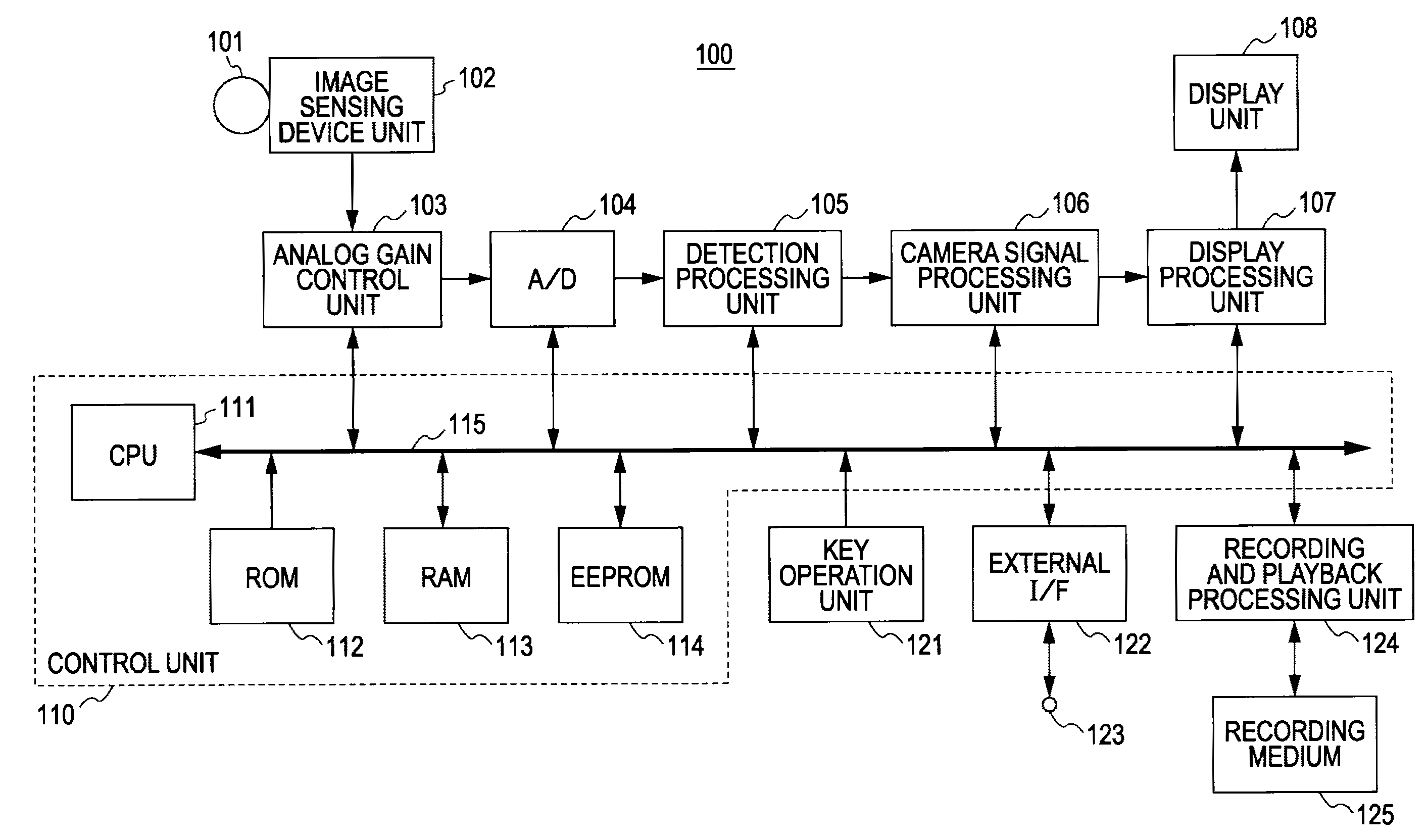
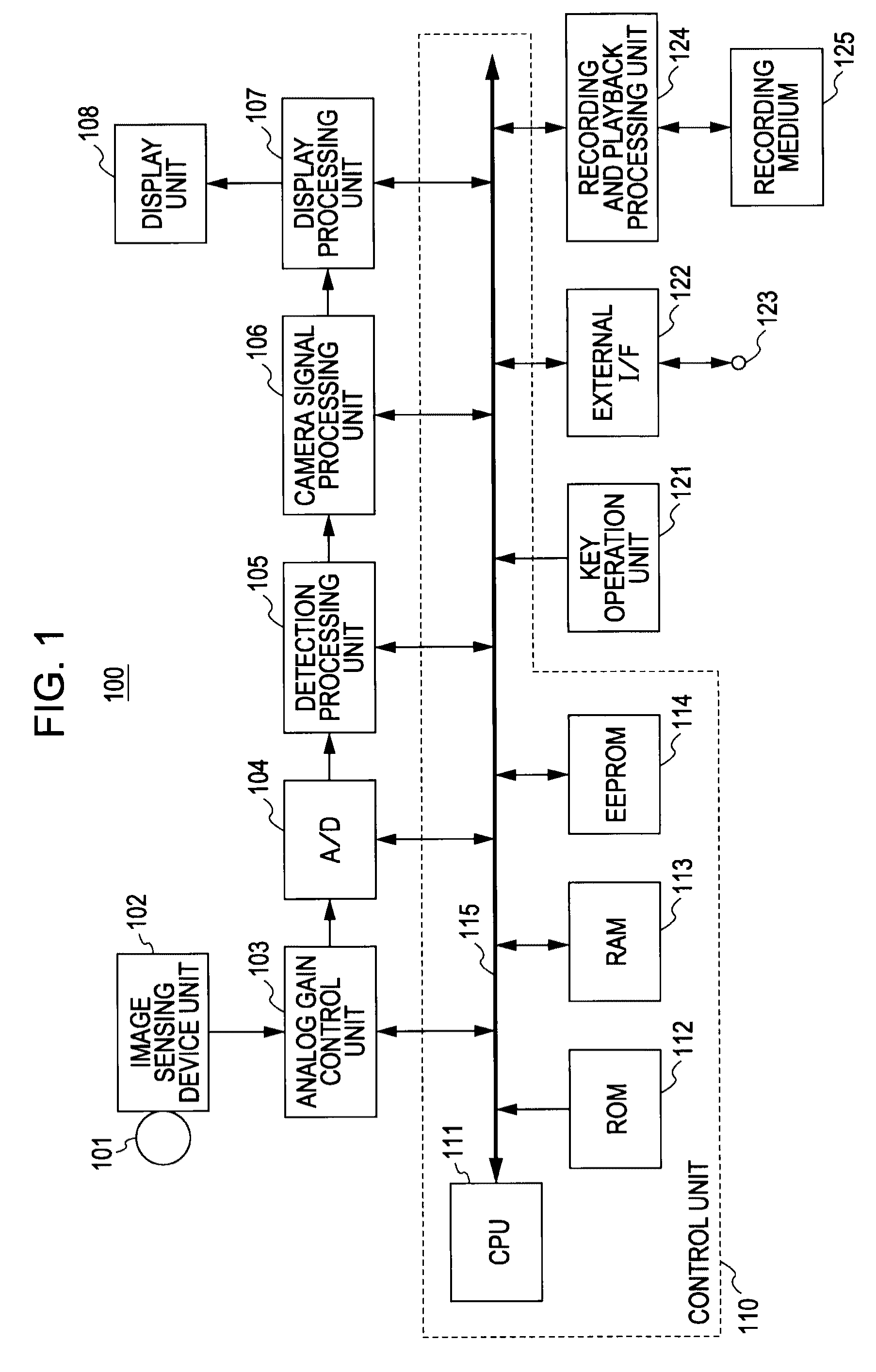
[0056]FIG. 1 is a block diagram of an image pickup apparatus 100 according to a first exemplary embodiment of the present invention. As shown in FIG. 1, the image pickup apparatus 100 includes a processing system of an image signal. The processing system includes a lens unit 101, an image sensing device unit 102, an analog gain control unit 103, an analog-to-digital (A / D) converter 104, a detection processing unit 105, a camera signal processing unit 106, a display processing unit 107, and a display unit 108. The image pickup apparatus 100 further includes a control unit 110, a key operation unit 121, an external interface (hereinafter referred to an “external I / F”) 122, an external input / output terminal 123, a recording and playback processing unit 124, and a recording medium 125.

[0057]The control unit 110 controls all units of the image pickup apparatus 100 according to the present embodiment. The control unit 110 is formed from a m...

second embodiment

Color Filter of Clearvid Arrangement

[0192]While the foregoing embodiment has been described with reference to the case where a color filter having color coding of the Bayer arrangement is used for a solid-state image sensing device of the image sensing device unit 102 in the image pickup apparatus 100 having the configuration shown in FIG. 1, the present invention is not limited thereto. For example, the foregoing embodiment can be applied to the case where a solid-state image sensing device using another type of arrangement, such as a Clearvid arrangement, is employed.

[0193]FIGS. 18A and 18B illustrate the color coding of a color filter. As described above or as shown in FIG. 18A, the Bayer arrangement includes lines each including alternately appearing R's and G's in the horizontal direction (i.e., RGRG . . . ) and lines each including alternately appearing G's and B's in the horizontal direction (i.e., GBGB . . . ). These two types of line are alternately arranged in the vertical...

third embodiment

Use of Color Ratio Signal

[0228]While the foregoing embodiments have been described with reference to the case where color noise is reduced by performing a noise reduction process on color difference signals (R−G) and (B−G), similar processing can be performed using a color ratio signal in place of a color difference signal. Thus, in a third embodiment described below, a color ratio signal is used in place of a color difference signal. In addition, description of the third embodiment is made when the third embodiment is applied to an image pickup apparatus having the configuration described in FIGS. 1 and 2.

First Exemplary Configuration and Overview of Processing of Demosaic Processing Unit 1063 (Use of Color Ratio Signal)

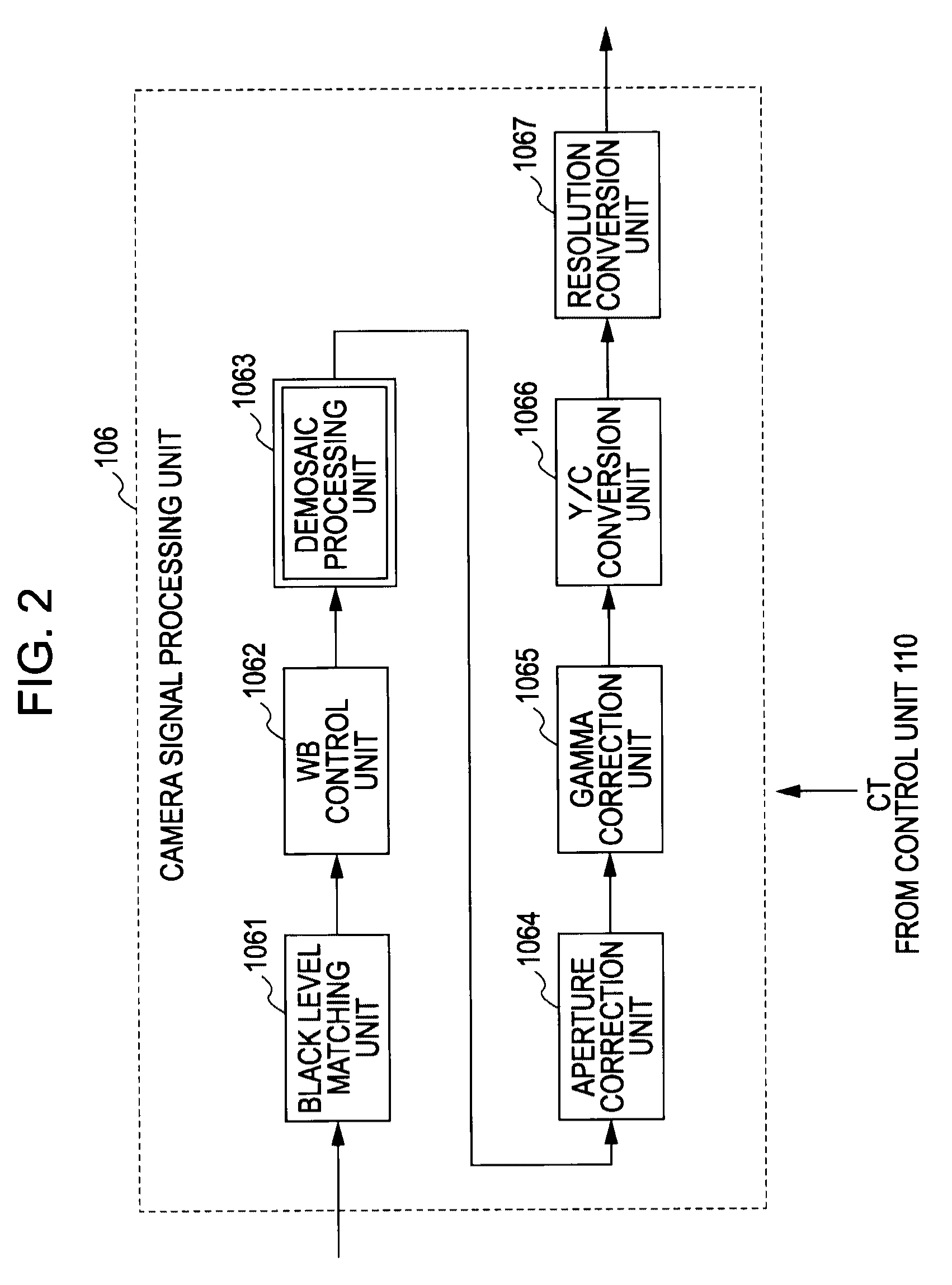
[0229]FIG. 24 is a block diagram illustrating a first exemplary configuration and the overview of processing of the demosaic processing unit 1063 of the camera signal processing unit 106 shown in FIG. 2 when a color ratio signal is used in place of a color differenc...


PUM


Abstract

An image pickup apparatus includes an image sensor including a color filter having pixels of different colors arranged in a predetermined order and a demosaic processor. The image sensor receives a subject image and outputs an image signal including color signals of the different colors. The demosaic processor generates color signals of the different colors for each of pixels of the image from the image signal. The demosaic processor includes a generation unit and a noise reduction unit. The generation unit performs computation using a target color signal representing a predetermined target color signal included in the image signal and a predetermined different color signal so as to generate a color-related signal that associates the target color signal with the predetermined different color signal for a pixel of the target color signal. The noise reduction unit performs a noise reduction process on the color-related signal generated by the generation unit.

Description

CROSS REFERENCES TO RELATED APPLICATIONS[0001]The present invention contains subject matter related to Japanese Patent Application JP 2007-330509 filed in the Japanese Patent Office on Dec. 21, 2007, the entire contents of which are incorporated herein by reference.BACKGROUND OF THE INVENTION[0002]1. Field of the Invention[0003]The present invention relates to a method and a program for reducing color noise in an image signal captured by a so-called single-panel image pickup apparatus including one solid-state image sensing device, such as a charged coupled device (CCD) or one complementary metal oxide semiconductor (CMOS) device.[0004]2. Description of the Related Art[0005]So-called single-panel image pickup apparatuses, such as single-panel digital still cameras and single-panel digital video cameras, include one solid-state image sensing device, such as a CCD or a CMOS device. The CCD or CMOS device includes a color filter having pixels of a plurality of colors arranged in a pred...

Claims


Application Information

Patent Timeline
Patent Type & Authority Applications(United States)
IPC IPC(8): H04N5/335H04N23/12H04N25/00
CPCG06T3/4015H04N9/045G06T2207/10024G06T5/002G06T5/20H04N2209/046H04N23/843H04N25/134G06T5/70
Inventor INABA, SEIJIROCHIBA, TAKUYAYONEDA, YUTAKA
Owner SONY CORP
Learn More