
Recovery of slurry unsupported catalyst

Active Publication Date: 2009-06-25
CHEVROU USA INC
View PDF101 Cites 14 Cited by
  • Summary
  • Abstract
  • Description
  • Claims
  • Application Information

AI Technical Summary

Problems solved by technology

The “bottom of the barrel”, or high boiling range material (i.e., vacuum residue) from crude oil, is difficult to convert into lighter products via conventional processes.

Method used


Image

  • Recovery of slurry unsupported catalyst
  • Recovery of slurry unsupported catalyst
  • Recovery of slurry unsupported catalyst

Examples


examples

[0065]The following illustrative examples are intended to be non-limiting.

Cross-Flow Filtration Example

[0066]A feedstock of used resid hydroprocessing slurry phase catalyst (1 to 10 μm) in unconverted heavy oil product was processed using eight stages of cross-flow filtration. The cross-flow filtration was conducted at 175° C. and 75 psig. The feed slurry solids content was 12 weight %. In each stage the feed oil was diluted with an amount of toluene equal to the original feed slurry. The resulting mixture was circulated through the cross-flow filtration module until sufficient oil and toluene permeated through the membrane to create a reconcentrated slurry of 25 weight % solids. A recirculating pump maintained a sufficient velocity through the tubes of the filter housing (greater than 10 feet / second) to avoid membrane fouling.

[0067]The design of the membrane was such that only the oil could permeate through the walls of the tube into the shell side of the bundle while the fine soli...


PUM

PropertyMeasurementUnit
Temperatureaaaaaaaaaa
Lengthaaaaaaaaaa

Abstract

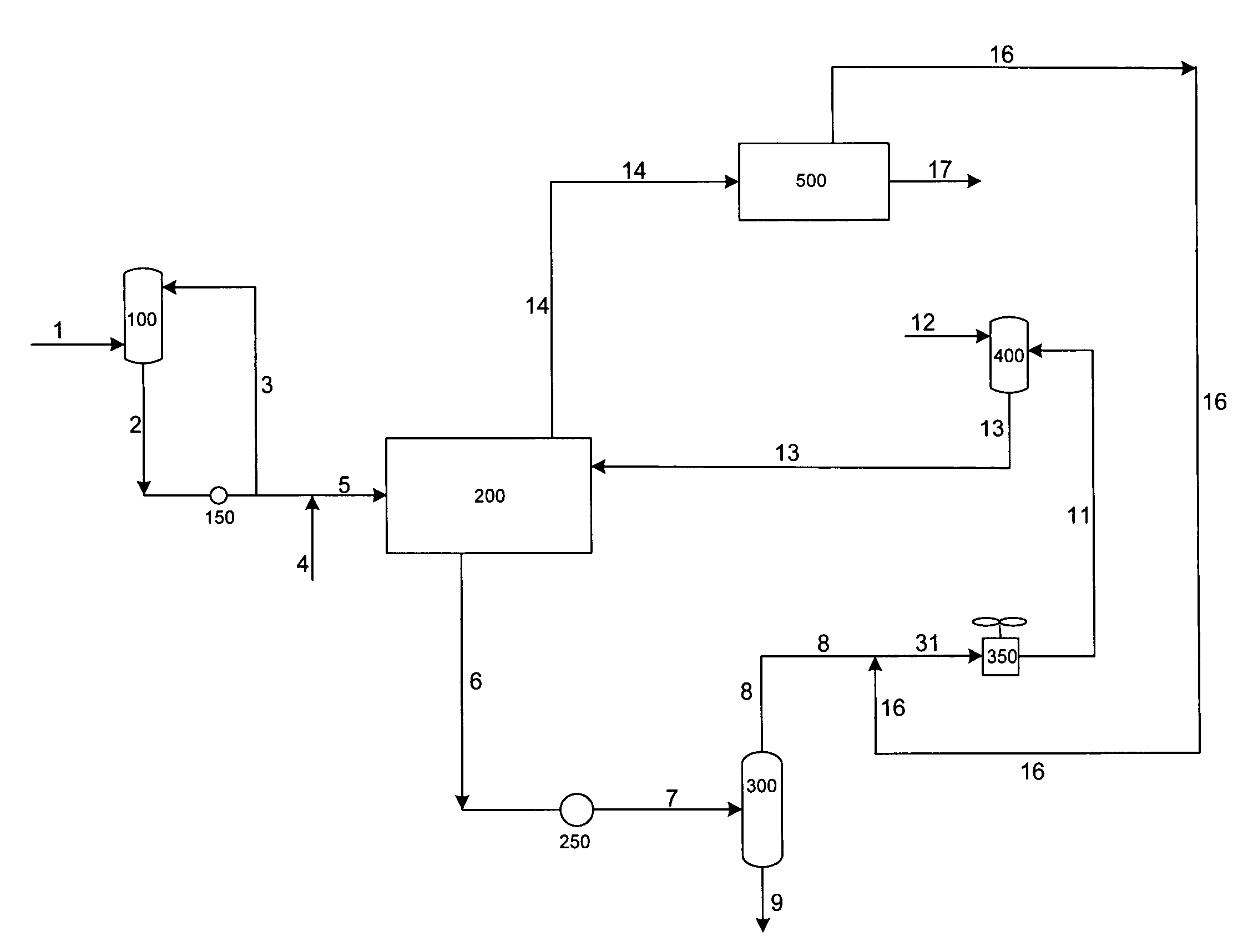
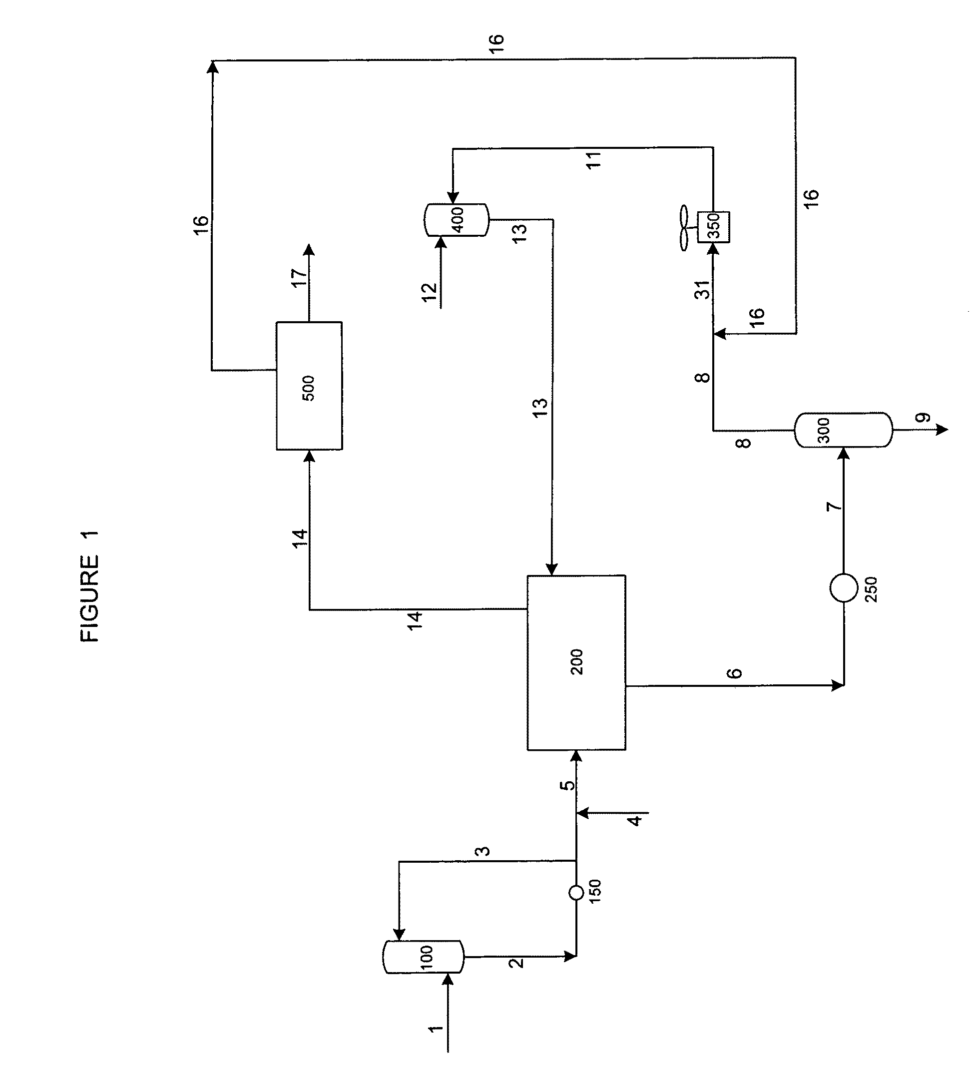
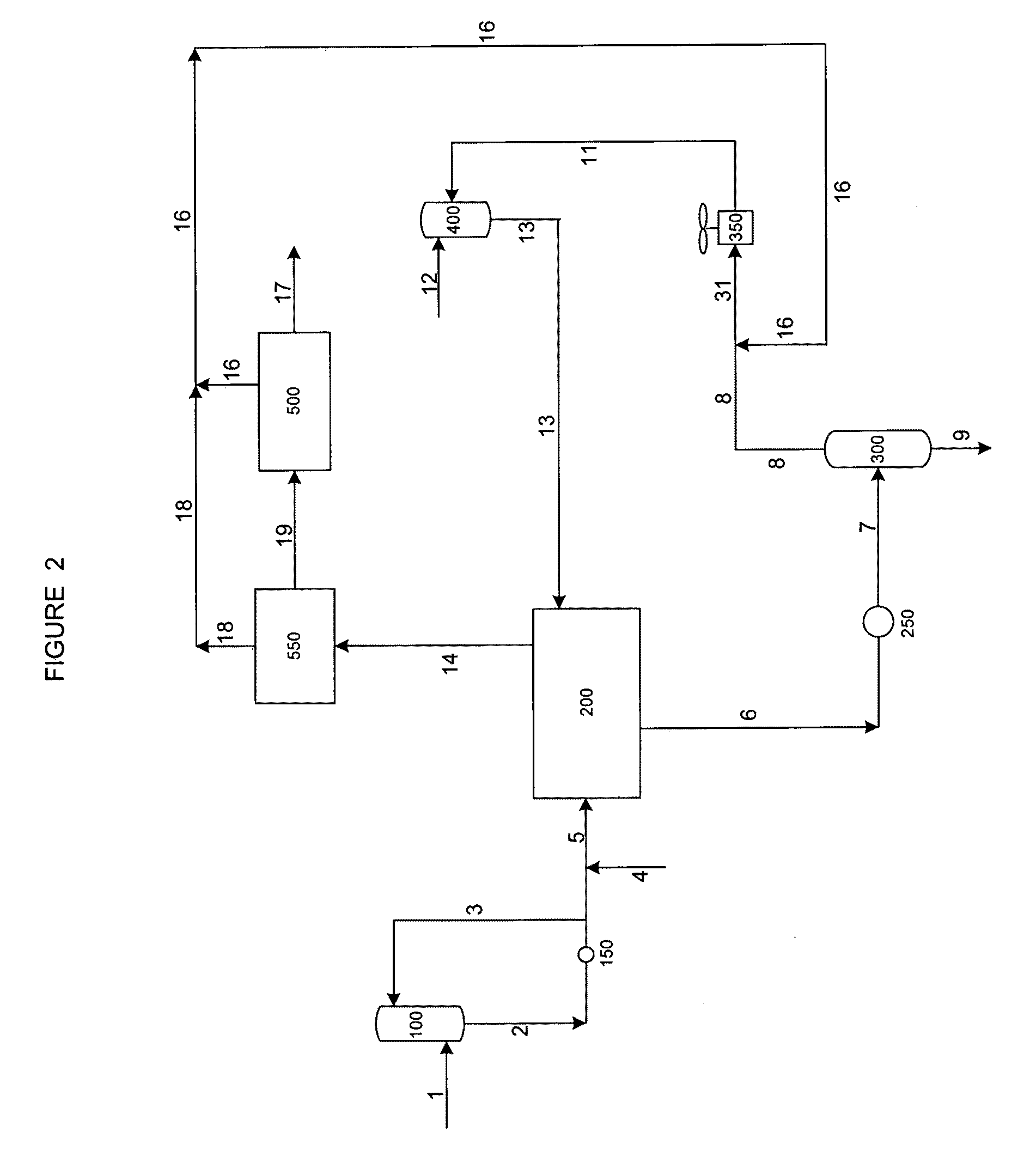
A method of recovering unsupported fine catalyst from heavy oil comprises combining a slurry comprising unsupported fine catalyst in heavy oil with solvent to form a combined slurry-solvent stream. The combined slurry-solvent stream is filtered in a deoiling zone. A stream comprising unsupported fine catalyst and solvent is recovered from the deoiling zone. Unsupported fine catalyst is separated from the stream comprising unsupported fine catalyst and solvent. The deoiling zone can comprise a membrane that is rapidly displaced in a horizontal direction.

Description

BACKGROUND[0001]As light oil reserves are gradually being depleted and the costs of development (e.g., lifting, mining, and extraction) of heavy oil resources have decreased, a need has arisen to develop novel upgrading technologies to convert heavy oils and bitumens into lighter products. The “bottom of the barrel”, or high boiling range material (i.e., vacuum residue) from crude oil, is difficult to convert into lighter products via conventional processes. Thus, what is needed are new technologies that achieve 90-100% conversion of vacuum residue, which would offer significant promise in resolving the problems associated with the disposition of large amounts of vacuum residue.SUMMARY[0002]In an embodiment, a method of recovering unsupported fine catalyst from heavy oil comprises filtering a slurry comprising unsupported fine catalyst in heavy oil in a deoiling zone. A stream comprising unsupported fine catalyst is recovered from the deoiling zone. Unsupported fine catalyst is sepa...

Claims


Application Information

Patent Timeline
IPC IPC(8): B01J38/48
CPCB01D61/142B01J38/48B01D65/08B01D2311/06B01D2315/10B01D2315/16B01D2321/2058B01J27/051B01J27/0515B01J38/72C10G31/09C10G31/11B01D61/147B01D2311/2669B01D61/146B01D61/1471
Inventor DA COSTA, ANDRE R.BRYAN, PAUL
Owner CHEVROU USA INC
Learn More